[
front |
purpose |
appendix
]
ATARI 800 XL memory expansion 192KB by Abbuc
Modification for full 130XE compatible
 Purpose:
The modification was mainly designed for turning the memory expansion in a
status which is full compatible to 130XE because there are some programs
especially demos which would not run at all. The reason is the wrong bank
handling in these productions.
The modification works as follows:
In a 130XE there are 2 lines of the PIA which are used for memory bank
switching. These are PB2 and PB3 (Pin 12 and Pin 13). There are 4 different
combinations, that means 4 banks a 16 kilobytes. These 2 lines are Bit 2
and 3 of the register $D301.
The Abbuc 192KB expansions uses beside PB2 and PB3 the lines PB5 and PB6.
So there are 16 different combinations, that means 16 banks a 16 kilobytes.
We just use 12 different combinations. So this expansion uses Bit 2,3,5 and
6 of $D301.
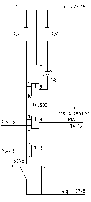
To have a full compatible 130XE we must mask out the lines PB5 and PB6
coming from PIA and set the ramdisk multiplexer in a special status that
just 64KB are available. This is the fact when the 2 input lines PB5 and
PB6 which came from PIA are set to logically HIGH. The conclusion is to use
an OR-Gate. 1 OR X (this is the PB line) is always 1 (means HIGH). Now
130XE mode would be active. 0 OR X is always X (means LOW or HIGH ofcourse).
Now full 192KB expansion would be active. We toggle over a switch one
input line of every gate to HIGH or LOW and can now set 130XE mode on or off.
A little LED is showing us the state of the memory expansion. LED ON means
full memory expansion (192KB) and LED OFF means 130XE expanded memory
(64KB).
Tested with:
This modification were tested with the original versions of: VENT,
ASSKICKER, TOTAL DAZE, NONE JM, JOURNEY, ATARI 130XE SHINY BUBBLES, ULTRA.
Important:
If you want to build this circuit you must interrupt the original PB5 (PIA-15)
and PB6 (PIA-16) lines from your memory expansion to PIA. The voltage supply can
you take from another IC of the memory expansion (e.g. the socket for U27).
What you need:
- 1 x IC 74LS32 (4 OR gates a 2 input lines)
- 1 x 2.2k resistor
- 1 x 220R resistor
- 1 x switch
- 1 x LED
- solder stuff, some wire, eventually a small plastic bag to put the
modification in (it must be isolated ofcourse inside the XL)
Appendix
XL256KB.DWG an AutoCAD R12 drawing (the original) of
the expansion+modification scheme
XL256KB.PS a postscript file of the above
MOD256KB.GIF a GIF picture of the modification scheme
MOD256KB.MIC a MIC picture (for Atari) of the above (not
yet implemented)
Any questions or comments? Just email me!
CubE - Last Updated: 23.09.1997
[
front |
purpose |
appendix
]
 Purpose:
The modification was mainly designed for turning the memory expansion in a
status which is full compatible to 130XE because there are some programs
especially demos which would not run at all. The reason is the wrong bank
handling in these productions.