
NOTE: If you are using Nick Kennedy's SIO2PC software, connect pin 6 of the 14C89 to the the PC RI pins. If you are using the newer APE software (v1.16), you can connect pin 6 of the 14C89 to either DSR or RI but change the software to reflect this. If you are using WinApe, use the DSR hookup. Works better.
 |
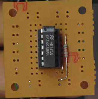 |
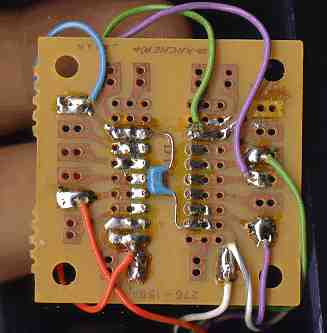
NOTE: In the left picture, the connection at the bottom left (the one that
looks like an upside down "L") is not connected to the trace above
it. This is the connection between pin 8 and the 1N4148 diode. You can just
see it in the lower right of the right hand picture (the diode). Also there
is a connection between pin 13 and pin 7 of the IC. Hard to see in this picture.
Check this for solder bridges!!
I have be asked by several people if I could do a "How to build a SIO2PC
cable". I hope the following will help. I'm not all that good at writing
"How To's" so things might seem strange in places. This is just a
rewrite of the 1 chip SIO2PC interface page so some thing might look the same.
I didn't have much time to do this and will refine it as time goes on. But for
now here is is, warts and all. You use this information at your own risk. If
you computers blow up, don't blame me. I will try to answer any and all questions
via e-mail but I do expect you to know the basic's of soldering and electronics.
If you don't, take a basic electronics course at your local junior collage.
You might even find that it is fun. Take care and remember to check all your
connections twice.
Please check the 1 chip SIO2PC page also. You will find more information there.
OK, the parts needed for the project are as follows,
| Discription | Radio Shack part number | Price | |
| 1 | A Radio Shack project box | 270-221 | $2.29 |
| 2 | A Radio Shack proto board. | 276-159A | $1.19 |
| 3 | A 1489, 14C89 or 75C189 IC | 276-2521 | $1.29 |
| 4 | A 5.6k 1/4 w resistor. (5k6 1/4w) | RSU11345014 | 5 / $0.49 |
| 5 | A .1uf Tantalum | RSU11295821 | $1.19 |
| 6 | A 1N4148, 1N914, 1N270 or any small signal diode. | 276-1122 or 276-1123 | 10 / $1.19 |
| 7 | A 14 pin IC socket (#276-1999A) | RSU11662004 | 2 / $0.59 |
| 8 | A DB-9 male socket (use one or the other) | 276-1537 | $0.99 |
| 8a | A DB-9 female socket (depending on your needs) | 276-1538 | $1.29 |
| Computer Gate part number | |||
| 9 | A PC Monochrome-DB9 Cable (9 pin ) | CM0909MF-3 | $1.29 |
| Atari part number | |||
| 10 | An Atari SIO cable cut in half | CB101276 or CB014122 | $8.00 |
Note: You can use either the male or female 9 pin connector. Which one depends on your application. I use the female because that is what I had cables already made up for. The diode can be just about any signal diode. I use the 1N4148 in all my projects. The 14 pin socket can be anything from low-profile to wirewrap. The .1uf cap can be a disc, monolithic or tantalum. So as you can see, the parts are not all that critical.
Note: the 75C189 is a direct replacement
for the 1498/14C89 and is easier to find ( except
that Radio Shack doesn't carry it, only the 1489). It also only
costs 39 cents. There are those out there that would sell you this part for
$3.00 or more. A total rip off. Anyway, for our application, the 1489 will work
quite well in this circuit.
The Monochrome-DB9 cable is a monitor extension or mouse extension cable. It is also wired straight through. This is what we want. It has a male 9 pin connector on one end and a female 9 pin connector on the other. You have to remember this is what I used and may not be what you will use. You might need a 25 pin connector on one end and a 9 pin on the other. I don't know how you have your PC set up. You may have to make your own cable. I did.
You will need an Atari SIO cable. The one with a black male 13 pin connector on each end. The one you plug into the Atari and a Disk Drive. Some of them have the connector shells bolted together (made in Taiwan) with a machine screw and nut and others are riveted together (Molex). Either one will do but you need one to make this work. If you don't have a SIO cable and don't want to pay about $8.00 for one, Best Electronics had the shells and connector for $4.95 but you would still have to build it. (If you can't find a SIO cable, you could wire the interface directly into the Atari) . If you were to build the SIO2PC interface into your Atari, you don't have to worry about any of this as the wires from the interface solder directly to the internal 13 pin male connector.
How to build it:
Now you have to decide how you are going to build your interface. It can be
anything from a used 35 mm film container (I did this and
filled it with Epoxy. Ended up looking like the one that came with the Critical
Connection or CP/M fame) to a Radio Shack project box
(I recommend a project box as it is larger and easier to work with)
or you can build it into your Atari.
Again, I recommend the project box method of building the interface but
however you do it is up to you.
First thing to do no matter what the final design is, is to insert the 14 pin IC socket in the center of the perf board. Press it down firmly. Turn the board over and tack solder pin 1 and 8 to the solder pads. Now turn the board back over and see if it is flush with the board. If it isn't, heat the 2 pins, one at a time, and gently press on socket. When the socket is flush with the board, turn it back over and finish soldering all the pins to the proto board.
OK, now insert the signal diode into the proto board so that the banded end is going to pin 8 of the IC socket and the other end is going to a pad that nothing else is connected to. Solder both leads to the pads and trim them back.
Insert the 5.6k 1.4 watt resistor into the board so one end goes to pins 14 and the other end goes to the empty pad the other end of the diode went to.
You should now have one end of the resistor soldered to pins 14 or the IC socket, the other end soldered to the clear end of the diode (on a free pad that nothing else is connected to) and the banded end of the diode soldered to pin 8 of the IC socket.
Now solder the .1uf monolithic capacitor between pins 14 and pin 7 of the IC socket.
Also solder a short jumper between pin 13 and pin 7 of the IC.
Double check all connections. There should be nothing connected to pins 1,2,3,4,5,6,9,10,11,12 of the IC socket and pins 7,8,13 and 14 should have items soldered to them. The hard part is now done.
Put the board aside. We will get back to it later.
The Project box method:
Put it inside your Atari method:
This is how I built it. Actually, I built the interface both ways just for the experience. Anyway, find a convenient place to install a 9 or 25 pin socket on the back of your Atari. The 800XL is the hardest of the bunch for this. Use a 9 pin socket and it is a little easier. I mounted the socket above the 13 pin SIO socket. Just make sure that where ever you put it, there is room for it.
Again, I used a Dremel Tool to cut out the plastic for the socket. Work slow and check the fit often. Then the socket just fits, clean up the hole and insert the socket. Mark the two mounting holes on either side and remove the socket. Select a drill bit the same size as the mounting holes in the socket and drill the case. You might find it easier to leave the socket in place and drill through the holes into the plastic. Either way, go slow. This is a very easy way to ruin your Atari's case.
Putting it all together:
If you used the Project Box method,
Solder the GREEN (pin 5) wire from the SIO cable to pin 1 of the IC
socket,
the PURPLE (pin 7) wire from the SIO cable to pin 4 of the IC socket,
the BLACK (pin 4) wire to pin 7 of the IC socket,
the BLUE (pin 10) wire to pins 14 of the IC socket
and the ORANGE (pin 3) wire to the junction of the 5.6k resistor and
the clear end of the signal diode.
NOTE: In the picture, the BLACK wire is the WHITE wire with GRAY TRACER.
Double check all connections!!
Now we have to install the serial cable that goes to the PC. Only problem here is that there is no standard color code for the wires. You will have to check them using a DMM or some other continuity checker.
If you are using a cable with a 9 pin connector on one end, you will have to figure out which color wires go to pins 2,3,5 and 9 . Write these down and then double check them again.
If you are using a cable with a 25 pin connector on one end, you will have to figure out which color wires go to pins 2,3,7 and 22 . Write these down and then double check them again.
In my case I make my own cables so I made a 9 pin serial cable with wire colors that matched the Atari SIO cable. So much easier.
For the 9 pin PC connector:
Solder the wire that goes to pin 2 of the connector to pin 3 of the IC.
Solder the wire that goes to pin 9 of the connector to pin 6 of the IC.
Solder the wire that goes to pin 5 of the connector to pin 7 of the IC.
Solder the wire that goes to pin 3 of the connector to pin 10 of the IC.
For a 25 pin PC connector:
Solder the wire that goes to pin 3 of the connector to pin 3 of the IC.
Solder the wire that goes to pin 22 of the connector to pin 6 of the IC.
Solder the wire that goes to pin 7 of the connector to pin 7 of the IC.
Solder the wire that goes to pin 2 of the connector to pin 10 of the IC.
If you installed the interface in your Atari,
Solder a GREEN wire from pin 5 of the SIO socket to pin 1 of the IC socket,
a PURPLE wire from pin 7 of the SIO socket to pin 4 of the IC socket,
and a ORANGE wire from pin 3 of the SIO socket to the junction of the 5.6k resistor and the clear end of the signal diode.
Double check all connections!!
For the 9 pin PC connector:
Solder the wire that goes to pin 2 of the connector to pin 3 of the IC.
Solder the wire that goes to pin 9 of the connector to pin 6 of the IC.
Solder the wire that goes to pin 5 of the connector to pin 7 of the IC.
Solder the wire that goes to pin 3 of the connector to pin 10 of the IC.
For a 25 pin PC connector:
Solder the wire that goes to pin 3 of the connector to pin 3 of the IC.
Solder the wire that goes to pin 22 of the connector to pin 6 of the IC.
Solder the wire that goes to pin 7 of the connector to pin 7 of the IC.
Solder the wire that goes to pin 2 of the connector to pin 10 of the IC.
Double check all connections!!
Now you have to find +5 vdc and ground. On the 800XL and 130XE this is easy. Locate capacitor C79. On the 800XL it is located to the right of U5 and below the SIO socket. On the 130XE, it is located between the cartridge socket and the SIO socket.
Solder a RED wire to the positive (+) side and a BLACK wire to the negative (-) side of the capacitor. Now solder the RED the other end of the RED wire to pins 13/14 of the IC and the BLACK wire to pin 7 of the IC.
Double check all connections!!
You can use double sided tape to secure the Proto Board to the top of a IC near the SIO socket.
Double check all connections!!
Look at the pictures, look at the schematic. This is not hard. Use your DMM and check that each and every connection goes where it should go then check it again.
When you are sure everything is wired up correctly, insert the IC in the socket making sure pin 1 of the IC goes into pin 1 of the socket. There is usually a small dot next to pin 1 or sometimes a small notch on the end of the IC. With the notched end pointing up, pin 1 is to the left when the pins are facing away from you. Look at the pictures!
OK, now either hook up the 9 (or 25) pin connector to your PC and the 15 pin black Molex connector to your Atari or if you built the interface into your Atari, plug the modem cable into your PC and the other end into your Arati.
Load APE or SIO2PC and set up an ART image in slot (or drive) 1. One that has DOS on it at first. You can get ATR images from the net or you can download one from this page. Read the manuals for APE and SIO2PC so you know how to do this.
Now for the moment of truth. Power up the Atari. If you did everything right, it should boot right up and either Basic or DOS will appear on your screen.
If nothing seems to work, power down the Atari and PC. Check all your connections again. Make sure there are no solder bridges on the Proto board. Make sure you installed the diode the right way. Band end to pin 8 of the IC.
The voltages below were taken from a working interface using a 14C89 chip. Ape was running on the PC and an Atari 130XE had finsihed loading DOS 2.6f. These voltades are approximate. Your mesurments may be off some but should be close ( plus or minus .5 volts).
| Pin 1 | + 2.5 volts DC |
| Pin 3 | 0 volts |
| Pin 4 | +2.9 volts DC |
| Pin 6 | 0 volts |
| Pin 8 | +5 volts DC |
| Pin 10 | -10 volts DC |
| Pin 13 | +5 volts DC |
| Pin 14 | +5 volts DC |
Make sure you understand how APE or SIO2PC software works and have it set up right. Read the manuals! and again Double check all connections!!
After you are sure that everything is working, you can use HOG RINGS to clamp the cables inside the Proto box. Don't have any HOG RINGS, use hot glue, use epoxy, use silicone glue. Doesn't really matter as long as you can't pull the wires out of the box.
That's it. Have fun and let me know if you don't understand anything or if you find any mistakes.
Where to Get the Software:
Also, the standard Atari disk image (which was around long before SIO2PC or the Atari 8-bit emulators) is ".DCM" - "DiskCommunicator". This can of course make boot disks. To boot your Atari with a DOS, you'll need a DOS disk.
Some DOSes available include:
Atari DOS 2.0
Atari DOS 2.5
MyDOS 4.5x
SpartaDOS 3.2x
(where "x" is some number or letter).
You can download MyDOS 4.5x or SpartaDos 3.2x here.
 Pin-outs for the DB9 and DB25 connectors.

 Signal Name                   DB9       DB25

 ---------------------------------------------

DCD (Data Carrier Detect)      1          8

RX  (Receive Data)             2          3

TX  (Transmit Data)            3          2

DTR (Data Terminal Ready)      4         20

GND (Ground)                   5          7

DSR (Data Set Ready)           6          6

RTS (Request to Send)          7          4

CTS (Clear to Send)            8          5

RI  (Ring Indicator)           9         22

Copyright © 1996,1998 Clarence Dyson.
All rights reserved.
Any reproduction, duplication, or distribution in any form
is expressly prohibited, except by consent of credited creators.