Have you ever wanted one of those nice ramdisk handlers built right into your operating system? How about a high speed SIO routine hiding in your OS code that you can use with your USDoubler? Maybe you needed the 400/800 OS for a favorite oldie that will not run on the XL operating system? Redefine the function keys right in the OS on your 1200XL? Modify the OS for Nir-PAL or the 65816? Built in monitor? Basic extensions? The list goes on and on. When these types of hacks are right in the OS, they don't take up any of your memory, don't require loading from disk and work with almost any DOS. So, how come you don't have them? Well, the reason you don't have any or all of these features now is twofold: you need an EPROM burner to make the OS EPROM and you can't put everything in one set of code (and expect it to work with a reasonable number of programs). This means that you would be required to open up your computer and change OS chips or have some sort of kludge, switching thing under the covers. What the average user needs is an upgrade that allows him to easily load any OS he requires at the moment and make it permanent thru power cycling (without buying an EPROM burner and burning dozens of OS chips). If you have something like that, you can whip up any kind of OS hack you like, effortlessly! So, here it is....
The Hack
SmartOS is a RAM chip that is powered by the Dallas Smart Socket. This "socket" is
actually a small PC board with logic and a backup battery that is built into a standard IC socket.
Once a low powered CMOS RAM is inserted in the socket, the battery maintains the data in the RAM
for up to 10 years -- making it equivalent to an EEPROM or EPROM. Once the RAM is loaded, you can
power off your computer, go on a two week vacation and everything you did will be there when you
power on again. The beauty of this setup is that the RAM is just that, RAM. You need no special
sequencing to write to it, no "programming", nothing. This is a perfect way to do last
month's Nir-PAL OS changes without the necessity of burning a new EPROM (along with a hundred other
things...).
More Features
In addition, the creator of this hack just couldn't resist throwing a programmable internal
cartridge in there -- as well as the address space from $D600 to $D7FE This gives you the
ability to boot with some thing other than BASIC rev.B as your internal cartridge. Normally, you
boot into BASIC when you power on your XL/XE, unless you hold down OPTION. With a programmable
internal cartridge, you can boot into any 8K cartridge on power up. Just load the in ternal
cartridge space with code and you're set! Your custom cartridge will survive power down as well as
errant code trying to overwrite what you have loaded -- just like the ROM that it re-places.
Also, the 512 bytes at memory location $D600 thru $D7FF, which are normally not available, will now
func tion as persistent RAM—great for those routines that won't fit anywhere else. The
SmartOS will work in any of the XLs or an XE, with a little extra work required on a 1200XL. It
will not work on a 400/800 -- sorry.
What Does It Do?
The upgrade allows you to switch select two functions. The first switch selects whether you use
your OS ROM (for those functions that your new OS does not get along with) or use the SmartOS. The
second switch write protects the RAM in the OS and inter nal cartridge address space ($D600 --
$D7FF are always writable). To give you a little more insight into how SmartOS functions, let me
take you thru my cur rent setup. I have the standard 800XL OS in ROM in my SmartOS board (any OS
may be used if it is just a 16K EPROM or ROM). I have loaded this Atari OS into my SmartOS RAM and
modified the color of my default GR.0 screen to green instead of blue. I also loaded the internal
cartridge space with my Atari Editor/As sembler cartridge and $D600 with the CHKSUM.OBJ code. With
the SmartOS switch in the ROM posi tion, my 1200XL boots up in blue with BASIC *(unless I hold down
OPTION, then it boots to DOS -- just like any other XL). In the RAM posi tion, the system boots a
green screen with ED/ASM running (or DOS if I hold OPTION). Placing the SmartOS write enable switch
in the "on" position will allow me to make any OS or cartridge code changes I wish while
leaving it "off" protects them uncondi tionally. With CHKSUM.OBJ in per sistent RAM at $D600,
anytime I want to re-calculate the OS checksum, I can $D600 from DEBUG without loading the
CHKSUM.OBJ from disk. Of course, YOU can do whatever you want with your OS, internal cartridge and
the 512 bytes at $D600. And, I am not limited to just my current configura tion -- a few minutes of
disk action and I can have anything my little heart desires. Like the drivers for an IDE drive. A
ramdisk handler. Floppy interface code. You name it. You write it. You load it. No EPROMs, no EPROM
burners, no waiting.
Operating Secrets
OK, so how does this work? As I mentioned, the heart of this project is a Dallas SmartSocket. This
intelligent device watches the power supply for any low voltage conditions. When it
"sees" the +5 volts beading towards zero (which means the power has been turned off), it
disables writing to the RAM and switches in it's internal back up battery. This keeps a glitch from
writing garbage as the power falls and you lose logic integrity (as well as during power up, for
the same reason). On powerup, once power is stable, the SmartSocket enables writing to the RAM,
disconnects his battery and off you go. The socket does not come with a RAM chip installed -- you
provide that. There are versions that include the chip in an integrated package, but I like the
ability to replace a bad RAM without throwing away the whole pack age. You also may need to dump
the contents of the RAM and the only way to do that may be to unplug it from the SmartSocket! I
used a 32Kx8 RAM on SmartOS, which gives me an extra 16K bytes to put things in, like the internal
cartridge and $D6xx. TheseSmartSockets come in capacities up to 512K bytes -- maybe a nice
permanent ramdisk for some future hack?
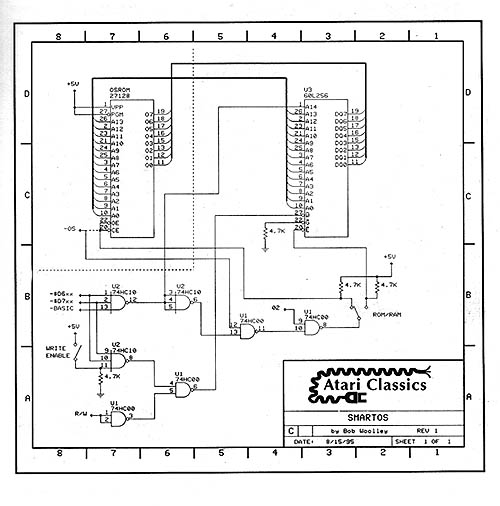
Techie Talk
So, this SmartSocket is wired in parallel with the existing OS ROM socket -- pin for pin. Except
for the -CS, R/W lines and the A14 address bit (refer to the schematic in Figure 1). The remaining
circuitry has two sec tions, chip select and write enable. Chip select is generated at Ul, pin 8
and switched to either the RAM or ROM thru the SPDT switch. See the - OS line from the board that
used to go directly to pins 20 and 22 on the OS ROM? This connection needs to be opened and
re-routed to pin 12 of U 1 where it will be ANDed with the inter nal cartridge and $D6xx memory
selects. From there, notice that 02 clock enables -CS to the memories (pin 9 of Ul). Running fast
RAM without 02 gating will cause subtle errors due to ad dress bit skew. Pins 1,2 and 13 of
U2 supply the remainder of the -CS logic. If either -$D6xx, -$D7xx or -BASIC are active, A14 of the
RAM is driven high, and -CS is generated. This has the effect of reading the OS ROM when you are
switched to ROM and you read any of those three areas (inter nal BASIC, $D6xx or $D7xx). You can
verify this with ED/ASM . At $D600, you will see the code from the OS ROM at $F600! For this
reason, the BlackBox and any other hacks that enable $D6xx will probably not work on SmartOS --
regardless of where you place the RAM/ROM switch. If you face this problem, disable $D6xx (and
$D7xx, if necessary) by disconnecting U2, pin 1 (and 2 -$D7xx) and wiring it to pin 13 (don't just
leave it open...!) Also disconnect the corresponding pin on U2, pins 9 and 10 (connect them to pin
11). The write enable section controls the R/W line to the SmartOS and in ternal BASIC portions of
the RAM. You need to be able to modify or load code in these addresses, but once loaded, they must
not be allowed to be altered. $D600 - $D7FF are enabled for writing thru pins 9 and 10 of U2, while
the switch wired to pin 11 of U2 enables all of RAM to be written. R/W is gated at pin 5 of Ul.
Wiring It Up
OK, enough theory stuff -- let's list some source pins. As stated earlier, all the lines from the
OS ROM are con nected to the Smartsocket except for pins 1, 20, 22, and 27. On my upgrade, I used
the second ROM site on a 1 200XL for the SmartSocket, cutting away the pins that were altered and
ad ding point to point wiring. I have also used a rip-off board on an 800XL, plug ging into the OS
ROM site. Either way, the wiring is similar (and will be covered next issue). The remaining
connections to the computer are:
Line Name Source
| -OS | pin 15 | CO61618 |
| -$D6xx | pin 9 | 74LS138 |
| -$D7xx | pin 7 | 74LS138 |
| -BASIC | pin 13 | CO61618 |
| -R/W | pin 36 | CO14806 |
| -02 | pin 39 | CO14806 |
And, of course, you need +5 volts and ground. Don't forget to pull the in ternal BASIC ROM, if you have one. I have used the Atari part numbers for the chips, although a 1 200XL does not have a C061618 chip (it's C060609). To do this hack on a 1 200XL requires you to replace your 60609 with a 61618 (as well as a little more wiring), OK? If you haven't done this to your 1 200XL, check in next issue or write to me.
Parts list:
| 74HC00 | 4x2 NAND |
| 74HC10 | 3x3 NAND |
| switches | SPST and SPDT |
| 4.7k | 1/4 w resistors |
| DS1213C | Dallas SmartSocket |
| 60L256/43256 | 32Kx8 low power static RAM |
Making It Work -- the OS
Once you complete construction, it takes a little fooling around to get the RAM loaded. Since you
will be starting with random data in RAM, you obviously cannot boot your computer with the switch
set to RAM -- you must start off in the ROM position. So, place the RAM/ROM switch in the ROM
position and the R/W switch in the disable (writing inhibited). The computer should boot OK in this
configuration, no matter what youhave in the RAM. You will not have an internal cartridge. The
first step is to propare an OS to load into the RAM. Let's just use the OS that's in your existing
ROM.
MVROM.OBJ
Plug in your ED/ASM cart and boot DOS 2.0. Do not use any other DOS unless you are positive
that it will not overwrite $4000 and above! It would be nice to be able to just go to DEBUG and
move the OS to $4000 from $C000, but that will certainly not work. The OS hides some code in $5000
that you need along with the $C000 data. For this function, I have included a short M/L program
called MVROM.OBJ. This routine properly copies your OS code into location $4000 where it can be
modified and/or written back into SmartOS RAM.
	0100 ; ***MVROM.ASM 8/02/95***		0360 ;

	0110 ;   MOVES ROM INTO MEMORY		0370	LDA #$$D8

	0120 ;					0380	STA $CC

	0130	*=  $0600			0390	BNE LP1

	0140 ;					0400 ;

	0150	LDA #$00			0410 MOVEPAGE LDA #$7D

	0150	STA $CB				0420	STA $D301

	0160	STA $CD				0430	LDA ($CB),Y

	0180	LDA #$C0			0440	STX $D301

	0190	STA $CC				0450	STA ($CD),Y

	0200	LDA #$40			0460	INY

	0210	STA $CE				0470	BNE MOVEPAGE

	0220	LDX #$FD			0480 ;

	0230	LDY #$00			0490	INC $CE

	0240 ;					0500	INC $CC

	0250 LP1 JSR MOVEPAGE			0510	LDA $CC

	0260	BEQ COMPLETE			0520	RTS

	0270	CMP #$D0			0530 ;

	0280	BNE LP1				0540 COMPLETE BRK

	0290 ;

	0300	LDA #$50

	0310	STA $CC

	0320 ;

	0330 LP2 JSR MOVEPAGE

	0340	CMP #$58

	0350	BNE LP2
To use the program from EDIT, Load MVROM.OBJ. Go to DEBUG and run MVROM.OBJ with G600. At this point, you can verify that your OS is now sitting in $4000 thru $7000. If you are going to make any changes to the Atari OS, you must re-calculate the checksum values stored in the code (see CHKSUM.OBJ). For now, just use the OS without modifying it.
MVRAM.OBJ
To copy the OS back into the SmartOS RAM, you need to use MVRAM.OBJ. This routine not only allows
the OS to be returned to its proper addresses, but allows for you to transfer control of $C000 -
$FFFF to RAM while you are running.
	0100 ; ***MVRAM.ASM 8/02/95***		0410	STA $CC

	0110 ;     MOVES MEMORY INTO RAM	0420 ;

	0120 ;					0430 LP2 JSR MOVEPAGE

	0130	*= $0600			0440	CMP #$58

	0140 ;					0450	BNE LP2

	0150	PHP				0460 ;

	0160	SEI				0470	LDA #$D8

	0170	LDA $D40E			0480	STA $CC

	0180	PHA				0490	BNE LP1

	0190	LDA #$00			0500 ;

	0200	STA $D40E			0510 MOVEPAGE LDA #$FD

	0210 ;					0520	STA $D301

	0220 LPSTART LDA $D01F			0530	LDA ($CD),Y

	0230	CMP #$06			0540	STX $D301

	0240	BNE LPSTART			0550    STA ($CB),Y

	0250 ;					0560	INY

	0260	LDA #$00			0570	BNE MOVEPAGE

	0270	STA $CB				0580 ;

	0280	STA $CD				0590	INC $CE

	0290	LDA #$C0			0600	INC $CC

	0300	STA $CC				0610	LDA $CC

	0310	LDA #$40			0620	RTS

	0320	STA $CE				0630 ;

	0330	LDX #$7D			0640 COMPLETE PLA

	0340	LDY #$00			0650	STA $D40E

	0350 ;					0660	PLP

	0360 LP1 JSR MOVEPAGE			0670	LDA #$FD

	0370	BEQ COMPLETE			0680	STA $D301

	0380	CMP COMPLETE			0690 LOOP JMP LOOP

	0390	BNE LP1				0700	.END

	0400	LDA #$50

	0410	STA $CC

	0420	;
This routine is basically the opposite of the MVROM.ASM code except for the initial setup from
lines 150 thru 240. Lines 150 thru 200 disable all in terrupts. We need to switch off the ex isting
OS and there will be no code for an interrupt to execute -- so, off they go. Lines 220 thru 240
wait forever for us to push the STAR key. This gives you an opportunity to set the ROM/RAM and write
enable switches before you load the RAM. Once you push START, the code from $4000 - $7000 is loaded
into $C000 - $FFFF and the computer is locked in a ticht loop. This final loop is to allow you to disable
writing to the RAM. Be sure that you do this or you may find some of your code overlayed when you re-boot.
So, from ED/ASM again, you should have loaded something into $4000 - $7FFF (hopefully a valid OS). Load MVRAM.OBJ
and go to DEBUG. G600 to execute MVRAM—the com puter will hang, waiting for the START key. Set the switches
to enable write and RAM. Ignore the screen garbage.... Push the START key. Disable write! Re boot on RAM -- you
should boot OK. Notice that you do not need to use MVROM to load the OS code for MVRAM. If you have a ROM image
on disk, you can load it into $4000 directly. In fact, this would be your normal pro cedure once you create a number
of OS images that meet your needs. In this case, the MVRAM,OBJ code could be appended to the OS image, with a run
address of $600 -- making an OS change a one step operation.
SETCART.ASM
To load the internal cartridge, you must be able to boot with the internal cartridge enabled and no cartridge plugged
in. If the current contents of the internal cartridge will not allow you to boot (see below), use ED/ASM and run
SETCART.OBJ as follows:
Boot ED/ASM cartridge. Load SET CART.OBJ -- screen will go off. Enable write. Push the START key. Disable write!
You should now be able to boot from RAM with no cartridge and the internal cartridge enabled.
	0100 ; **SETCART.ASM 8/09/95**

	0110 ; LOADS SBFFC IN CART.

	0120 ;

	0130	*= $0600

	0140 ;

	0150	SEI

	0160	LDA #$00

	0170	STA $D40E

	0180	LDA #$FD

	0190	STA $D301

	0200 ;

	0210 LPSTART LDA $D01F

	0220	CMP #$06

	0230	BNE LPSTART

	0240 ;

	0250	LDA #$FF

	0260	STA $BFFC

	0270 LOOP JMP LOOP

	0280	.END
Permanent RAM
The last operation that you may wish to do is load code into the new RAM at $D600 tbru $D7FE This RAM is used just like any
other RAM loca tion as long as you have the ROM/RAM switch in the RAM posi tion. These addresses are always enabled for
writing and no special precautions must be taken to load them. Use them for data, tables or. code any time you want -- the
data will survive power off and cold boots forever (or, your money back...:)
Things to Ponder
Some quirks to be considered when using SmartRAM:
The OS tests all 48K of lower memory when you do a cold boot. If the SmartRAM is write enabled during a cold boot, this
memory test will zero the entire internal cartridge RAM area. This not only wipes out your internal cartridge, but also
causes any subsequent cold boots to fail. It seems that the OS checks for a cartridge by two methods, one of which is to
look for $00 at loca tion $BFFC. If you have written a $00 in there (from the RAM test), you set. the cartridge flag.
This branches you into the checksum routines for the cartridge (which has been wiped out!). No matter if you hold down
OPTION or not, the code tries to checksum a non-existent cartridge. Rats—you now cannot boot with SmartRAM selected
unless you have a real cartridge plugged into the cartridge port. And, with a cartridge plugged in, you cannot write into
the SmartRAM cartridge area... Hmmmmm.... This is the reason you need SETCART.ASM. This little routine does nothing other
than store $FF into the SmartRAM cartridge area at $BFFC. This allows you to boot with SmartRAM enabled and no cartridge
plugged in -- which you need to do in order to load code into the SmartRAM cartridge area ($AOOO-$BFFF).
The OS code calculates the check sum of all the bytes in ROM every time you boot your computer. When you are making modifications
to the OS, you must therefore re-calculate this check sum and store it in the appropriate loca tions of the OS. Otherwise, you
will be presented with the self-test screen every time you power on. To make it easier to re-calculate and store the checksum,
I have included some .OBJ code that does a nice .job of automatically correcting your checksum. It was given to me by Tim Patrick
and has been very useful over the years, so I hope he doesn't mind if I pass it along to the rest of the users. Unfortunately for
you subscribers. that did not order disks, I do not have the CHKSUM.ASM code, only the .OBJ, so you will need to D/L it from CIS
or your local BBS (if they have it). For disk subscribers, there are two ver sions of GHKSUM—one that uses $600 and one that
resides in $D600 (per manent SmartRAM). CHKSUM.OBJ runs from $600, while CSUMD6.OBJ runs from $D600.
Coming Attractions
OK -- that's about all for this issue. There should be enough information here to get some of you guys up and run ning. Next issue,
I'll go over in some depth just how to build one of these upgrades. I'll cover the use of the tools . you will need, special
1200XL modifications, PCB layout, construction tech niques and integrating this hack with the IDE interface (IDE interface... what
IDE interface?)
This is a hardware modification that will give you the ability to easily modify the code in your OS and save it permanently in a RAM module. The key element of this upgrade is a clever piece of hardware from Dallas Semiconductor called a SmartSocket, from which I shamelessly stole the name of this hack, SmartOS. The project will be presented in two parts, overview and detail. The first installment will contain enough information for an experienced hardware buff to build a SmartOS along with the code segments required to set it up. The second half of the series will be more of a primer for you less handy folks out there. It will include tools and test equipment use, construction techniques, general sources for parts and goodies, and have lots of pictures to follow. With them, you should be able to get yourself into real trouble!