
From the pen of AC's "occasional columnist" Ben Poehland comes the final, gutwrenching word on cleaning up video problems in all the XL-series computers, as The Alchemist brutally reveals the scandalous acts of the Sunnyvale Butchers. Clean video at last for the 600XL, 800XL and the 1200XL owners!
We'll do S-V 2.0 first; it's the easiest of the upgrades and yields spectacular results. You might elect to stop after doing S-V 2.0, since going further with 2.1 brings diminishing returns for more work. I guess I need to make a disclaimer here: if you try any of these mods and botch it, tough krinkles. The Alchemist, Staff and Publisher of AC won't be responsible for people who mangle their machines (or themselves) trying to do this stuff. You'll need resistors, capacitors, heat-shrink tubing, and a panel-mount SPST mini toggle switch, all available at Radio Shack. Buy the resistor assortment pack #271-312: it contains all the resistors you'll need in exactly the proper wattage and physical size, with plenty left over for future hacks. Figures 3 and 4 show the "before and after" schematics. The schematic of Fig. 4 essentially represents the upgrade as it will appear in all three XL machines. Only the component designations will differ.
OK, let's get our hands dirty. Remove the six screws from the bottom of the case and separate the case halves. Remove the motherboard fastening-screws, and wiggle the board free of the case. Make sure you discharge yourself to some large (preferably grounded) metal object before removing the motherboard RF shields, and handle it only by the exposed broad foil ground plane strip around the edges. Place the board on a conductive surface (damp newspapers will suffice), and orient it according to the diagram in Fig. 5.
|
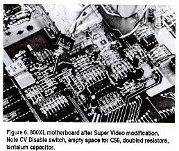
NOTE: This is what the completed Super Video Modification for the 800XL should look like. |
By The Numbers...
Study Figures 5-7 and refer to them for the following steps:
Step 1. Locate resistor R53. It will be either a 100 ohm resistor (brown-black-brown-gold)
or a 390 ohm resistor (orange-white-brown-gold). Remove it and solder a 75 ohm resistor (violet-green-black-gold)
in it's place.
(This restores the mono output impedance to the correct value.)
Step 2. Locate the 180pF glass capacitor C56 and snip it off the board with fine wire cutters. (This improves video high-frequency response.)
| NOTE: C56 above, may or may not be present. The schematics I have don't show it. |
Step 3. Locate R116, a 51-ohm resistor (green-brown-black-gold) and remove it. Solder a 2.2-ohm resistor (red-red-gold-gold) in it's place. (This improves output current flow to Q3, which is "starved" for current in Atari's original design.)
Step 4. Select a 10uF/16V tantalum capacitor and bend the leads outward. Notice one lead is marked with a (+) sign. Position this part above the board so the (+) lead touches the bottom of the R116/2.2-ohm combination while the (-) lead touches the top of R66. The leads are too long. Cut them off right where the leads contact the respective resistors, then solder the cap in place. (This improves Q3's transient response and filters noise from the supply line feeding the video output.)
Step 5. Locate R66, a 100-ohm (brown-black-brown-gold) resistor. Replace it with a 75 ohm resistor (violet-green-black-gold). (This lowers the impedance of the color signal output to the correct value.)
Step 6. Now we'll install the CV Disable switch. The purpose of this switch is to enable composite video for users whose color monitor accepts composite video only. Those who use luma or luma-chroma interfaces should toggle the switch to disable composite video. A cleaner signal, free of color clocking interference that makes the screen background grainy, will be obtained. Cut two 8" lengths of wire and strip 1/4" insulation from one end of each. Solder the stripped ends of each wire to the two lugs on the switch. Twist these wires lightly as shown in Fig. 6. At the unattached ends, snip off 1" from one of the wires, then strip 1/4" insulation from the ends of both wires. Set the switch assembly aside temporarily.
Now locate R56 on the motherboard, a 75-ohm resistor (violet-green-black-gold). We want to de-solder the left end of this resistor (DON'T cut it!). Get a good grip on the left end with needle-nose pliers, then apply your soldering iron to the joint at a 45-degree angle so it firmly contacts both the resistor lead and the solder pad. Allow sufficient time for the joint to heat up-about 10 seconds, the solder will start to bubble. With the iron still in place, pull up smoothly but firmly with the pliers: the resistor should come up easily. If it doesn't, allow a good 5 minutes for everything to cool down, then try again.
Once the left end of R56 is free, use the needle-nose pliers to form the free lead end into a loop. Then bend the resistor into a vertical position supported by the end still soldered to the board. Clear the vacated hole of solder. Now retrieve the prepared switch assembly and solder the longer wire to the vacated R56 circuit board hole. Solder the shorter switch wire to the loop at the top of R56.
Step 7. Now we'll install the chrominance pick-off resistor. Select a
100-ohm resistor (brown-black-brown-gold), and to one end of it apply a length
of insulation (stripped from wire) leaving only 1/8" of the lead exposed.
Cut a 5" length of wire and strip 1/4" insulation from each end, then
solder this wire to the un-insulated end of the resistor. Now experiment a little
to find the smallest diameter heatshrink tubing that will fit over both the
solder bulge and the resistor body, then snip off a length sufficient to cover
the bare lead from the resistor body to the solder junction plus an extra 1/4"
to overlap both ends. Slip the tubing into place, then warm it by holding the
assembly 1/4" above your hot soldering iron while slowly rotating it for
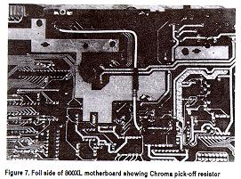
even heating. The tubing will contract to make a neatly insulated assembly (see
Fig. 7). DO NOT use tape to insulate this resistor!
Solder the short end of the prepared resistor to the junction of R67-R68 on the foil side of the board. Solder the other end to pin 5 of the monitor jack, routing the wire through the gap between the ground plane foils as shown. Keep the wire close to the board. I later added a dab of hot-melt glue at the bend in the wire to secure it in place.
Step 8. On the rear panel of the case, at a point 1" above the bottom of the panel and midway between the monitor jack and the TV output jack, drill a hole for mounting the composite video enable/disable switch. The exact size of the hole depends on the diameter of the mounting stem of the switch. This completes the S-V 2.0 modification for the 800XL.
800XL S-V 2.0 Checkout
Place the bare board on a clean insulated surface (Formica kitchen tabletops work well) and attach the power supply and video cables (a good monochrome monitor with luma connected is preferred here). Turn on the power (yes, the 800XL boots up fine without keyboard or shields installed). You should see BASIC's "READY" notice and cursor appear on your screen, brighter and clearer than ever before. Adjust the monitor's brightness and contrast controls so you can see the entire display, including the background. Work the CV Disable switch back and forth as you study the screen background. You should see a grainy background appear and disappear as you toggle the switch. Some monitors reveal this better than others, and it's harder to see if the focus control on your monitor is out of adjustment. On color monitors you might not see it at all.
If you're satisfied with your accomplishments to this point and don't wish to go further, reattach the RF shields to the board (route the switch wires out near the RF modulator), reinstall the board, fasten the switch to the rear panel, and close up the case. However, if you aren't afraid of more work and would like to push video performance to its very limit, keep that iron hot and move on to Super Video 2.1!
Copyright © 1993
Atari Classics
1161 Bay St.
Alameda, CA 94501

