
From the pen of AC's "occasional columnist" Ben Poehland comes the final, gutwrenching word on cleaning up video problems in all the XL-series computers, as The Alchemist brutally reveals the scandalous acts of the Sunnyvale Butchers. Clean video at last for the 600XL, 800XL and the 1200XL owners!
S-V 2.1 for the 600XL
For the remainder of this article I'm going to revert to a more truncated style of presentation in the hope of saving page space.
Physically, S-V 2.1 in the 600XL is tedious, as boardspace allotted to the video components is rather a minuscule piece of real estate. Consequently the video circuitry is densely packed, and you'll have to mount most components vertically. With this upgrade we have a lot of labor to perform, since we'll be adding all the parts Atari swindled from us as well as replacing the bungled ones they installed.
The resistors, capacitors, and switch are all available at Radio Shack. You'll need three 2N3904 (MPS3904) transistors, also at Radio Shack (#276-2016). If the 3904 is unavailable you can substitute the 2N2222 (MPS2222), #276-2009. Don't take the specs and diagrams printed on the packaging too seriously: a 2N3904 and MPS2222A I purchased both showed the collector and emitter leads reversed on the package diagram. (I verified the leads on the actual parts with a click tester; they were correct. I long ago learned not to trust data furnished with the Rip-Off Shack's overpriced parts.) When installing these transistors, line up the flat side of the part with the flat side in the outline screened on the board.
You'll also need a 5-pin DIN board-mounted socket: that's a problem. These sockets are used in all IBM computers and are available dirt-cheap at every electronics outlet in the world. Except Radio Shack. Best Electronics sells them for $1.00 apiece. The problem is that no mail-order parts vendor wants to bother with an order for a single part that costs less than a buck. You'll have to be creative. Band together with friends or your usergroup and buy a whole bunch of them, or combine your order with other items. Perhaps some shrewd operator will stock up on them and offer them to AC readers through the Swap ads in the back of this magazine.
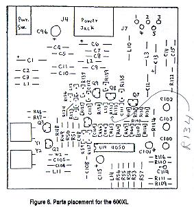
Refer to Fig. 8 for the following steps:
Step 1. De-solder and clear all the board holes for the following components:
C111 J7  Q8   R128 R131 R134 R137

C112 L12 Q9   R129 R132 R135 R138

C113 Q7  R124 R130 R133 R136 R139
Step 2. Remove the following components from the circuit board and clear the vacated holes of solder:
C109, C110, C115, L14, R59, R123, R127, R14, channel selector switch.
Step 3. Install the following components at the indicated locations:
| Part | Value | Code/Mark | Location |
|---|---|---|---|
| Blank space | - 0 - | - - - | C109 |
| Capacitor, ceramic | 100pf | 101 | C110 |
| Capacitor, ceramic | 5pf | 4.7 or 5 | C111 |
| Capacitor, ceramic | .001uf | 102 | C112 |
| Capacitor, ceramic | 100pf | 101 | C113 |
| Capacitor, radial electrolytic | 220uf/16V | 220/16 | C115 |
| Switch (1) | SPST | - - - | L12 |
| Resistor | 2.2 ohms | red-red-gld-gld | L14 |
| Transistor | 2N3904 | 2N(MPS)3904(2222) | Q7 |
| Transistor | 2N3904 | 2N(MPS)3904(2222) | Q8 |
| Transistor | 2N3904 | 2N(MPS)3904(2222) | Q9 |
| Resistor | 1.5K | brn-grn-red-gld | R59 |
| Resistor (2) | 75 ohms | [brn-grn-brn-gld] x 2 | R123 |
| Resistor (2) | 75 ohms | [brn-grn-brn-gld] x 2 | R124 |
| Resistor | 2.2K | red-red-red-gld | R127 |
| Resistor (3) | 6.2K | [orn-blk-red-gld] x 2 | R128 |
| Resistor | 1K | brn-blk-red-gld | R129 |
| Resistor | 2.2K | red-red-red-gld | R130 |
| Resistor | 1K | brn-blk-red-gld | R131 |
| Resistor | 1K | brn-blk-red-gld | R132 |
| Resistor | 3.3K | orn-orn-red-gld | R133 |
| Resistor | 10K | brn-blk-orn-gld | R134 |
| Resistor | 220 ohms | red-red-brn-gld | R135 |
| Resistor (2) | 75 ohms | [brn-grn-brn-gld] x 2 | R136 |
| Resistor (2) | 75 ohms | [brn-grn-brn-gld] x 2 | R137 |
| Resistor | 3K | orn-blk-red-gld | R138 |
| Resistor (4) | 4.7K | yel-vio-red-gld | R139 |
| Resistor | 1K | brn-blk-red-gld | R140 |
Notes:
(1) Two 7" lengths of stranded wire, lightly twisted, from switch lugs to L13 holes.(CV disable switch)
(2) Synthesized value: two 150-ohm resistors in parallel.
(3) Synthesized value: two 3K resistors in series.
(4) Designated R141 in Atari diagrams (schematic error).
Step 3. On the foil side, cut the foil connection between pins 2 and 5 of J7.
Step 4. Install the 5-pin DIN jack on the component side of the board. Depending on the particular style of unit, it might be necessary to file down the two front pins to get them in the holes. Solder all the pins, including the two front ones.
Step 5. Now we bring out the luminance signal to the jack. Twist together two 150-ohm resistors (brn-grn-brn-gld), solder the leads together, and place insulation (removed from wire) over all but 1/8" of the exposed lead length on both sides. On the foil side of the board, solder one end of this part to the junction of R123-R124 and the other end to pin 1 of the output jack J7. Depending upon lead length, you might have to add a short length of insulated wire to one end of this part. Mine barely made it without adding extra wire.
Step 5. Now we'll bring out chroma to the jack. Select a 100-ohm resistor (brn-blk-brn-gld) and place insulation (removed from wire) over all but 1/8" of the exposed lead length on both sides. On the foil side of the board, solder one end of this part to pin 5 of output jack J7, and the other end to the emitter lead of Q9. This lead is on the left when you look at Q9 face-on.
Step 6. On the bottom half of the RFI shield, locate the square hole where the channel selector switch used to be. Cut out all the metal above this hole, extending to a distance of about 2mm on either side of the hole, and all the metal below the hole down to the bend. You'll end up with a square-looking version of the big notch already present for the adjacent power supply jack.
We have to cut another notch for the CV Disable switch. Viewing the RF shield from the rear, cut a notch 18mm wide commencing at a point 3mm to the left of the hole already present for the RF output jack. This notch should extend all the way to the bend in the metal. You'll lose a shield mounting tab, but that doesn't matter.
Cutting these notches isn't easy. I used a Moto-Tool equipped with an emery cutting wheel to do a neat job, and I filed down burrs and sharp edges with a fine Swiss file. Tin snips might also work but would probably warp the metal. Heavy-duty wirecutters might also suffice, though they might not be much good for anything else when you're done. Sheet metal is a pain.
Step 7. Now we have to make holes in the rear panel outer case, starting with the hole for the video jack. Measure off a point exactly 21mm to the left of the leftmost edge of the power connector hole. Make an indent there to start your drill bit, then drill a 3/4" hole. If all goes well you'll completely obliterate the existing rectangular opening where the channel selector was. In my experience it's better to have an opening too large than too small. Square off the edges of the hole with a round Swiss file. On my unit I filed off the "2 - CHAN - 3" lettering, which is now meaningless.
Now for the CV Disable switch hole. At a point 25mm from the bottom of the rear panel, and 13mm to the left of the leftmost edge of the RF modulator hole, drill a hole for your switch. The diameter of this hole should be just slightly larger than the mounting stem of your switch (I used a 3/8" bit). If you follow these instructions exactly, everything should fit perfectly when you reassemble the case.
[NOTE: Steps 3,3,4,5,5,6 and 7 should be numbered 3, 4, 5, 6, 7, 8 and 9]
Checking Out The S-V 2.1 600XL
Boot up the bare motherboard with your favorite monitor as described earlier for checking out the mod on the 800XL. After upgrading my 600XL I was pleased to observe a crisp display in both mono and color whose characteristics were identical to the results I obtained with the 800XL, including the function of the CV Disable switch. After you're satisfied everything is running OK, reassemble the shields and case and close it up.
Those of you who still want to use the TV interface on your 600XL might be concerned about the loss of the channel selector switch. It's actually still there: removing the switch is equivalent to leaving the selector permanently set on the Channel 3 position (I haven't verified that). If you're really very fussy about this you can always run some wires from the channel selector switch holes in the vicinity of J7 out to another SPST switch mounted on the rear panel-if you can find room for it! Having gone to all this trouble installing the electronics for interfacing my 600XL to a nice crisp monitor, I don't give a hoot about the TV interface any more.
Perspectives On 1200XL video
Despite the abundance of extra parts in the 1200XL video section, it turns out the basic design of the 1200XL video amplifiers isn't much different than the ones in the 800XL and 600XL. In all three machines color is handled by a group of three transistors, while the baseband monochrome/composite output is a separate single-transistor circuit. All these transistors are 2N3904 types. The table below summarizes the schematic designations of these transistors and briefly describes their functions:
| Function | 600XL | 800XL | 1200XL |
| 1st color amp | Q7 | Q2 | Q19 |
| 2nd color amp | Q8 | Q4 | Q8 |
| Color output | Q9 | Q5 | Q7 |
| Mono/CV output | Q6 | Q3 | Q11 |
Atari's most serious design and manufacturing flaws occurred in the baseband mono circuit, which screwed up both mono and color.
What sets the 1200XL apart from the other XL machines is an extra three-transistor circuit (Q16-Q17-Q18) whose input connects to the color sync signal at GTIA pin 25. The output is emitter-coupled to the color amp circuit via a diode (CR19) to Q19. It took me a while to dope out what this was for, but once I caught on my imagination was gripped in a spell of astonished wonder. This extra little circuit boosts color saturation. And The Alchemist is here to tell you its effect amounts to video magic. If Atari had included this extra 25-cents' worth of parts in all its 8-bit machines, and hadn't squandered it by butchering the rest of the video circuitry, the Atari 8-bit could have blown away the competition hands-down. Especially for color graphics and games!
Curing the video defects in the 1200XL was no easy task: the gremlins were well-entrenched with multiple lines of defense, and they fought The Alchemist tooth and nail every inch of the way. But, as General Grant discovered in the American Civil War, the secret of victory lay in lessons learned from the battles fought. That secret is to achieve a balance between three conflicting elements of the color output, which are: 1.) color saturation; 2.) color shadows; and 3.) sharpness (signal strength and bandwidth). The main rule of the game is: "Anything you do to improve one of these elements will necessarily degrade performance of at least one, and probably both, of the other two." Insofar as the monochrome amplifier plays a key role in achieving the best color display, improving the color display automatically results in optimized monochrome performance.
My philosophy was to tolerate a certain amount of color shadows while maximizing sharpness and saturation. This approach provides maximum benefit for both mono and color users. Color shadows don't affect the monochrome display at all, while the optimized signal provides the best possible screen sharpness for text. On color displays, the eye tends to be more forgiving of object shadows if the picture is sharp and clear arid full of brilliant color. Object shadows in the color display seem to me a video artifact that varies according to the particular combination of colors on the screen, being absent with some combinations and more noticeable with others. The S-V 2.1 upgraded 1200XL still exhibits some color shadow artifacting, but I'm gambling most people won't notice it while they're playing a fast-moving videogame on a crisp, vividly colored screen. In short, you game freaks will have a field day playing color games on a 1200XL upgraded to S-V 2.1XL using a luma-chroma interface.
Copyright © 1993
Atari Classics
1161 Bay St.
Alameda, CA 94501

