

|
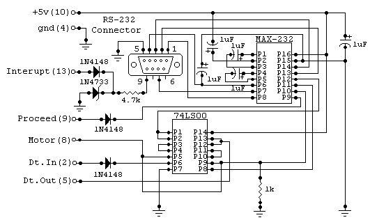
The following is the description of how to build an RVerter compatible interface. I have never actually seen one so I derived most of this from tracing the connections inside an SX212 modem to determine what pins on the SIO interface corresponds to which on the RS232 connection (except the data lines which are obvious). This interface should work with any RVERTER (or BOBVERTER) handler. It may work with SX212 handlers or software but may not support all of the baud rates. Handlers are available alone and with some terminal programs like Bobterm. I am not sure if all handlers support 19200 baud but I have used my interface connected via a null modem cable to an IBM to transfer files at 19200 baud and have had no problems. I tried 38400 baud (by patching the handler) and too many errors were generated. I also connected the SX-212 to the interface instead of the SIO connection and had no problems. I actually built this by lightly super gluing the two IC's into a large DB9 hood and soldering the connections. I would NEVER try that again even though it did work (after fixing a couple of mistakes). I planned on eventually filling it with EPOXY but I didn't and pray nothing ever comes loose. The cable I built was a SIO cable (from my fried XM301 modem) with the interface built onto the other end in a male DB9 connector. I was able to use a ready made IBM cable to connect to the modem. I also built a null modem cable and gender changer. This interface in unable to communicate at the same time as other I/O is occurring. This is typical unless you have an interface that connects to the XL/XE parallel buss. NOTE: CTS is not supported so you cannot use RTS/CTS handshaking. Only XON/XOFF is used. When transferring files between computers, if you use a normal transfer protocol this will not cause a problem. No responsibility is assumed for any damage resulting from the building or use of the interface.
		Parts:

		------

      IC1      MAX232

      IC2      74LS00

      R1       1k 1/4 watt

      R2       4.7k 1/4 watt

      C1,C2    4.7uf 16 volt

      C3,C4,C5 10uf 16 volt

      D1,D2,D3 1N4148

      ZD1      1N4733 5.1 volt
Optional (only needed to be able to detect the ring detect signal from the modem): This is not tested and hopefully it does not need to be inverted.
Be sure to not polarity of the capacitors. Note: The positive leg of C4 does go to ground since the other leg will be a negitave voltage. Pins for the RS232 are for a 9 pin connector. With this connector you can use a standard 9 to 25 pin cable and connect to a modem or a null modem cable to transfer files. You can substitute a 25 pin connector using the table below. If you plan on using it for file transfers, you can wire in the null modem cable before the jack. NOTE: The 9 pin connections ARE NOT the same as the Atari 850 interface. The are the same as used on most modern IBM type computers. Change the gender of the plug as desired.
       9 Pin     25 Pin

       ----------------

         1         8

         2         3

         3         2

         4         20

         5         7

         6         6

         7         4

         8         5

         9         22


       RS232 Definitions:

       ------------------

       CD    = Carrier Detect (inp)

       D.In  = Date In (inp)

       DSR   = Data Set Ready (inp)

       DTR   = Date Terminal Ready (out)

       D.Out = Data Out (out)

       CTS   = Clear to Send (inp)

       RI    = Ring Indecator (inp)
Null Modem Connections:
Last Updated 1/95 Contact: cp576@cleveland.freenet.edu |
All parts can be purchased from either JDR or Jameco Electronics.


