Build a Low-Cost Printer Interface
16K Cassette or Disk
by Paul S. Swanson
16K Cassette or Disk
by Paul S. Swanson
The step up to a printer can be very costly, especially if an Atari 850 Interface Module is required. Of the printers not requiring an interface offered by Atari, the 1027 Letter-Quality Printer may prove too slow, and the 1025 Dot Matrix Printer has no graphics capability. There are many used Centronics-compatible printers available at very reasonable prices; but the 850 Interface you need to use them adds another $200 to the cost.
Even if you already own an 850, there are other potential problems with using it to drive a printer. One example is trying to run a printer in combination with a modem connected to the Interface Module. While the modem is in use, any attempt to send data to the printer will cause the system to lock up. This occurs because the 850's RC232C post depends on serial bus interrupts, effectively disabling all other I/O activity while the port is open.
Fortunately, it is possible to connect a printer to your Atari without an 850 by using a pair of joystick ports. It's not a perfect solution, but it does solve the problem mentioned above.
A stick-port printer interface requires a special software handler, which must be installed in your system before you can use the printer. Therefore, this interface will not work with any commercial software that cannot be LOADed from BASIC. The machine-language handler is located in the upper half of page 6 (starting at address 1664 or $680 hex), so it will not work with any program that uses this area of memory.
These restrictions eliminate a few uses for the interface, but several others remain. For instance, programs you write yourself in BASIC can use this interface, and can be LISTed to a printer through it. Public-domain software written in BASIC can also benefit, because the handler can be initialized before the application is LOADed. This interface also allows you to print while an 850 modem channel is open, if your printer is fast enough to keep up with incoming data. Unlike other stick-port interfaces, my design uses only two ports instead of three or four, so it is fully compatible with Atari's new XL line of computers. And because 850 Interfaces are hard to come by nowadays, this low-cost interface might make a good temporary backup while you wait for your 850 to arrive.
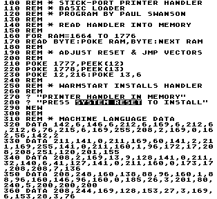
The hardware part of the stick-port interface is just about the simplest possible. All you need are three plugs. One connects to your printer; you will have to determine which type of plug your printer requires. The other two are standard 9-pin joystick plugs, available from any Radio Shack store for $2.49 each (catalog #276-1538). The plugs are wired together with a 12-conductor ribbon cable. I cheated by using a 14-conductor cable, leaving two conductors unused.
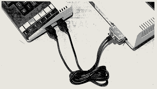
Refer to the documentation that came with your printer to determine the pin assignments for the plug at that end of the cable. This interface requires data lines 0 through 6. If the printer takes 8 data bits, the manual should indicate whether you should make Line 7 high or low for a 7-bit interface. If it doesn't say anything about it, connect Line 7 to ground.
You'll also need a strobe line and a busy line as well as the ground line. If no busy line is present, the "acknowledge" line may work. The ground line must be connected to the ground on your computer for reference.
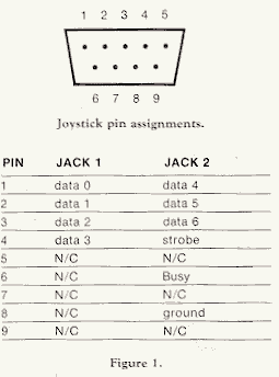
Figure 1 shows how the wires should be connected to joystick ports I and 2. The pin numbering on the plugs can be easily determined by holding the connector so that the 5-pin row is on top, with male connectors facing towards you and females facing away. With the connector oriented in this manner, pin 1 is in the upper left corner. Pins are numbered left to right across the top, and continue left to right across the bottom.
Using Figure 1 and your printer documentation as a guide, get out your soldering iron and connect the ribbon cable to the three plugs. Be very careful to solder the wires and pins correctly.
Before installing the software part of the interface, you can test your wiring with some immediate-mode commands in BASIC. BASIC is too slow to check the acknowledge line on most printers, but the following tests can be used to verify all of the other lines.
POKE 54018,56:POKE 54016,255:POKE 54018,60
POKE 54016,141:POKE 54016,13
For printers with active low strobes, swap the 13 and 141. Bit 7 is the strobe line in this interface, so 141 (which is 13+128) is used to set that line high.
Two things could have happened when you hit RETURN. Nothing is one possibility. If this is the case, check first to see if the printer is actually turned on and, if required, selected for "on-line." If your printer has a self-test function, you may want to try that also.
Some printers require line feeds. If yours is one of these, try the following immediate-mode commands:
POKE 54016,138:POKE 54016,10
If everything is connected, the printer is online and still nothing happens, it's time to start checking your wiring again. The most likely error is soldering the ribbon wires to the printer plug in reverse order.
There are too many different types of printers around to cover all of the possibilities. If your printer has a parallel interface and doesn't follow the standards I'm describing, then you'll have to do a little research. There should be enough information in this article and in your printer's manual for you to figure it out yourself. Things that could vary include the polarity of the strobe and busy lines, and the presence or absence of bit 7. In a few instances, you may find that the data are inverted, in which case you must subtract from decimal 128 the 7-bit code for each character. This isn't very common, so your printer manual will probably mention it if applicable.
Your programming now has direct control over the voltages on the wires you connected. If you POKE a value into location 54016, its binary representation will be converted to a pattern of voltages on the wires. A binary 0 should correspond to less than 0.8 volts, binary 1 to at least 2.0 volts. This can be tested with a voltmeter by connecting its ground to the ground line of the interface cable, and using the "live" probe of the meter to measure each of the eight data lines.
Once everything checks out, you are ready to install the software portion of the interface. The Atari computer makes this an easy job for anyone familiar with assembly language. Listing 1 is the assembly source code for an Epson printer interface.
This printer handler makes use of a set of utility routines in the Atari operating system called CIO (Central Input/Output). CIO handles most of the logic required to implement the OPEN, CLOSE, PUT and GET commands for the printer. If you perform a PRINT to the printer through BASIC, CIO will automatically break the print line down into individual characters, so that the interface will have to deal with only one at a time. LPRINT is a special BASIC command that is the equivalent of an OPEN/PRINT/CLOSE sequence. CIO will take care of all of these details for you.
CIO uses tables to find the locations of device handlers and other information it needs. The handler tables start at hexadecimal address $31A. Each I/O device is represented by three bytes. The first byte is the ATASCII representation of the device name, "P" or hex $50 in this case. The other two bytes are a pointer to the handler entry table, which can be located anywhere in memory.
An entry table contains a sequence of 2-byte addresses called vectors, which tell CIO where to branch for each supported function. The vectors must be arranged in the order shown in Lines 360 through 410 in Listing 1 (addresses $680 through $68B). GETB, which gets one byte from the device; STATUS, which returns a device status code in response to a BASIC STATUS command; and SPECIAL, used to implement anything not covered like XIO commands, are not used in this handler, so these vectors all point to a routine that returns a "function not implemented" error code to CIO. CIO uses the 6502 Y register to pass error code numbers, with 1 being the "no error" indication.
The handler's OPEN and CLOSE routines (Lines 500-570) simply define the function of the pins on the joystick ports. OPEN configures the pins for output and CLOSE redefines them as input, which is their default condition. OPEN and CLOSE use the 6502 A register to pass the port definition byte, which is 255 ($FF) to OPEN the ports and 0 to close them. Both routines also use the PASTEUP (Port A Setup) subroutine to configure the ports.
PUTBYTE (740-1050) is the routine that actually sends a character byte to the printer. It begins by checking the busy line to make sure the printer is ready. For printers with busy lines that are active high, the BNE instruction in Line 760 must be changed to a BEQ instruction.
Line 770 of Listing 1 is not required, and may be changed to a CLI or NOP instruction. Leaving the SEI instruction in place disables all other nonmaskable interrupts from occuring during the PUTBYTE routine. If you want to use the printer concurrently with a modem, change Line 770 to a CLI ($58).
Setting up bytes for printing requires translation of the Atari End-Of-Line character (155 or $9B hex). This is checked first at Lines 810-830. Next, the high-order bit is set with the ORA #$80 instruction in Line 850. For printers with active low strobes, this must be changed to AND #$7F to clear the high-order bit. The STA PORTA instruction sends the processed byte to the printer.
After a character has been sent, the printer must be given time to respond. The JSR JINIT instruction in Line 870 refers to a dummy routine set up to waste 8 machine cycles or about 2 microseconds, after which time the strobe line polarity is reversed by clearing bit 7 with AND #$7F. For active low strobe printers, change this instruction to ORA #$80.
The next sequence (930-980) is a timing loop that waits for the printer's busy line to respond. Epson's busy line is active high. Change the BNE PUT3 instruction in Line 960 to BEQPUT3 if your printer's busy line is active low. This routine will return a timeout error code ($8B) to CIO if the printer fails to acknowledge by the time the loop counts down to zero.
The three unimplemented functions mentioned above are handled in Lines 1090-1140. This routine returns an error 146 if called.
The initialization routine is the final part of this program. Lines 1180-1270 find the current entry for the "P" device in the handler table at $31A, and replace it with the address of the new handler table. The JMP out of the initialization routine at Line 1410 will be defined by the BASIC program that loads the handler into page 6. This will make it possible for the handler to re-initialize itself whenever the SYSTEM RESET key is pressed.
In Listing 2, the assembly routine in Listing 1 has been converted to decimal DATA statements. Try not to add or delete any bytes if you must change the machine code to fit a different printer protocol. If you must add or delete, be sure to alter the calling addresses in the handler entry table. Note that the entries in the table are the addresses of the entry points minus one.
The BASIC program first POKEs the machine-language code into its proper location in memory. Then the JMP vector at the end of the handler is adjusted to point to the address contained in DOSINI (location 12 or $OC hex). This assures that the normal SYSTEM RESET routine will be completed after initializing our handler. Finally, the system's DOSINI vector is "stolen" to point to the beginning of the handler's initialization code.
The last statement executed by the BASIC program is NEW, which clears the BASIC loader from memory. The interface handler is still tucked safely away in page 6, but it has yet to be installed. Press the SYSTEM RESET key and your new interface software will be initialized and ready to use.
The stick-port printer handler should act almost the same way as the normal 850 Interface handler as far as BASIC is concerned. One important difference is that the OPEN command does not check to see if a printer is actually on-line. Normally you can an OPEN command to see if a printer is available. For this new handler, a similar test can be performed by TRAPping a PRINT statement and looking for an error 138 (device timeout). All other functions (including LPRINT) should work identically to the resident printer handler.
If you're programming specifically for the stick-port interface and your printer's busy line is active high, you can use BASIC's STRIG(O) function to check for a "printer ready" condition. With the printer plugs connected, STRIG(O) will return a value of 0 if and only if the printer is connected, active and ready for output. Otherwise, STRIG(O) will return a value of 1.
There are many possible uses for this type of printer interface. In addition to using it as a replacement for an 850 Interface, or for printing while using a modem, it also provides an easy way to add a second printer to your system. You'll have to alter some of the assembly code to identify the second printer as a new device. Instead of searching for an ATASCII "P" in the OS handler table, look for an unused table entry, represented by a $00 in the handler identification byte. Insert some other identifier, like "Q." You can then OPEN the "Q:" device and PRINT to it when you want the output to go to the second printer.
This general scheme can be used to implement almost any 7-bit parallel output device. It doesn't even have to be a printer. It could be, for example, another computer. You could use such a system to transfer data from your Atari to another micro simply by PRINTing it. The restriction is that only seven bits are supported. There are also a number of plotters and other devices that could make use of this type of interface.
Your printer may provide a couple of signal lines that are not supported by this interface. A fault line is one example. This line is used to indicate that the printer encountered an error. This line isn't really necessary because the busy line will always reflect the fact that the printer is not ready. If you want to attach a fault line so that it can be checked, connect it to pin 6 on controller jack # 1 and you will be able to read its state by using STRIG(O).
With a little imagination, the ideas presented in this article can be used to connect your Atari to almost anything that uses 5-volt logic. Even serial devices could be accessed by writing the routines required to convert back and forth between serial and parallel. With serial addressing, it is possible to interface to devices capable of both input and output. Enough lines are available to implement a direction control bit and bidirectional transfers of four-bit groups. By applying the principles introduced here, connecting other devices to your Atari should present very few problems.
INTERFAC.ASM is available in ATASCII format.
0100 ;         JOYSTICK PORT PRINTER HANDLER
0110 ;         EPSON VERSION
0120 ;         -----------------------------
0130 ;         Program by Paul S. Swanson
0140 ;
0150 ; OS equates
0160 ;
0170 HATABS = $031A  ; device handler address table
0180 PACTL = $D302   ; port A control register
0190 PORTA = $D300   ; port A I/O register
0200 TRIG1 = $D011   ; stick trigger 1 register
0210 ;
0220 ; Program equates
0230 ;
0240 ORIGIN = $0680  ; start of new handler
0250 DUMMY = $FFFF   ; dummy address for JMP vector
0260 ;
0270     *=  ORIGIN
0280 ;
0290 ; Start of new handler table
0300 ;
0310 NEWTABLE
0320 ;
0330 ; These are the new handler vectors,
0340 ; presented in the order CIO expects them
0350 ;
0360     .WORD OPEN-1
0370     .WORD CLOSE-1
0380     .WORD GETBYTE-1
0390     .WORD PUTBYTE-1
0400     .WORD STATUS-1
0410     .WORD SPECIAL-1
0420 ;
0430 ; JMP to init (also expected by CIO)
0440 ;
0450 JINIT
0460     JMP EXIT    ; dummy init routine
0470 ;
0480 ; OPEN subroutine
0490 ;
0500 OPEN
0510     LDA #$FF    ; set port A to "output"
0520     BNE PASETUP
0530 ;
0540 ; CLOSE subroutine
0550 ;
0560 CLOSE
0570     LDA #0      ; set port A to "input"
0580 ;
0590 ; Configure port A
0600 ;
0610 PASETUP
0620     LDX #$38
0630     STX PACTL   ; enable data direction control
0640     STA PORTA   ; specify "input" or "output"
0650     LDA #$3C
0660     STA PACTL   ; reset addressing mode
0670     LDA #$FF
0680     STA PORTA   ; clear the port
0690     LDY #1      ; OK status for CIO
0700     RTS
0710 ;
0720 ; PUT BYTE subroutine
0730 ;
0740 PUTBYTE
0750     LDY TRIG1
0760     BNE PUTBYTE ; wait for busy line
0770     SEI
0780 ;
0790 ; Process byte to send
0800 ;
0810     CMP #$9B    ; is this an Atari EOL?
0820     BNE PUT1    ; ignore if not
0830     LDA #$0D    ; else convert to printer CR
0840 PUT1
0850     ORA #$80    ; set for active high strobe
0860     STA PORTA   ; and send byte to printer
0870     JSR JINIT   ; waste a few cycles
0880     AND #$7F    ; end the strobe pulse
0890     STA PORTA
0900 ;
0910 ; Wait for busy line
0920 ;
0930     LDY #0
0940 PUT2
0950     LDA TRIG1   ; printer ready?
0960     BNE PUT3    ; yes - continue
0970     DEY
0980     BNE PUT2    ; else keep waiting
0990     LDY #$8A    ; timeout error code
1000     CLI
1010     RTS
1020 PUT3
1030     LDY #1      ; no errors
1040     CLI
1050     RTS
1060 ;
1070 ; Unimplemented functions
1080 ;
1090 GETBYTE
1100 STATUS
1110 SPECIAL
1120     LDY #$92    ; error code
1130 EXIT
1140     RTS
1150 ;
1160 ; Initialization code
1170 ;
1180 PINIT
1190     LDY #0      ; init index
1200 PLOOP
1210     LDA HATABS,Y ; get an ID byte
1220     CMP #'P     ; is this the "P" entry?
1230     BEQ FOUND   ; yes, so change entry
1240     INY         ; otherwise skip 3 bytes
1250     INY
1260     INY
1270     BNE PLOOP   ; and keep looking for "P"
1280 ;
1290 ; Change table entry so that
1300 ; it points to our new handler
1310 ;
1320 FOUND
1330     LDA #NEWTABLE&255 ; lsb of table addr
1340     STA HATABS+1,Y
1350     LDA #NEWTABLE/256 ; msb
1360     STA HATABS+2,Y
1370 ;
1380 ; The following JMP vector will be
1390 ; set up when the handler is loaded
1400 ;
1410     JMP DUMMY
1420 ;
1430 .END 100 DATA 108,146,639,83,868,89,965,234
,98,830,76,951,957,358,88,6490
250 DATA 68,94,603,341,111,78,424,918,
87,237,633,480,4074