

So,you got the SmartIDE working? Want to add an IDE hard drive? OK. Let's do it.
Inside or Out?
You have two options: mount
the drive inside your 1200XL or leave it outside. There is very little to do if
you mount it external to the 1200XL and not too much extra to put it under the
covers. I prefer it inside myself, so I'm going to lay it out that way for you.
At some point in time, I'll do an IDE only upgrade where you don't need all the
SmartOS hardware and the IDE code can be burned into the OS ROM.
Little Enuf
Refer to the SmartIDE schematic.
The only additional parts needed to add an IDE drive are the 40 pin IDC header
and the two 75 ohm resistors on U4. Piece of cake. Just be sure to mount the
resistors as close to U4 as possible and keep your 40 conductor cable under 24
inches. The rest of the modification deals with mounting the drive.
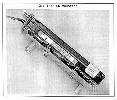
In the 1200XL
Although I used a 2.5 inch
drive in the unit on our cover, there is enough room for the more common 3.5
inch HDs. Either way, the internal Atari power components have to go. This
includes the regulators, filter capacitors, rectifier and the heat sink. You
must also remove the modulator, and the AC power input connector.
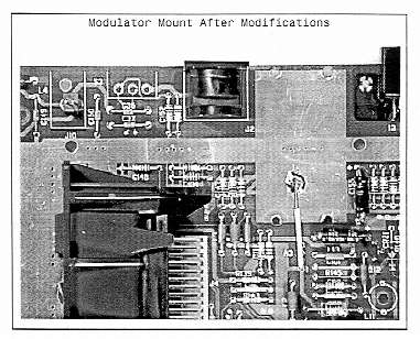
Pulling Teeth
First, the modulator. This is a
bear to remove since it 1/16th inch gap between the board and the bottom of the
modulator. What you are doing is bending the motherboard away from the lug so
don't go king kong here. Now melt the other outside lug and pry it up a little.
Cut the four signal leads at the back of the modulator and work the two rear
lugs out of the board. Eventually, you will be able to completely remove the
front two pins and the job will get easier. Take your time and be patient. Don't
crack your motherboard! Clear the four signal pins at the rear. *** very
important *** Add a jumper from the last pin (marked with a 1) to the ground
surface that was under the modulator. Refer to the photograph of this step. The
modulator is used as a ground distribution conductor and if you don't add the
wire, you get a terrible video problem!
New +5v Input
Next step is to remove the 9vac
power connector - just unsolder it with a 40 watt iron. I then soldered in a two
pin polarized connector that will serve as the +5 volt input for the 1200XL.
Orient the connector so that the ground is on the left and the +5 volts is on
the right.
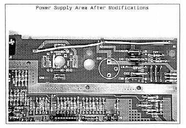
Old Power Parts
Now, the power. Pull C39 (the
large filter capacitor) and cut the legs off of the rectifier (CR12). Disconnect
the regulators at Al and A2 and demount the heatsink entirely. Clear out all the
solder from the removed component mounting holes and add 22 gauge or larger
jumper wires to the motherboard. The jumper starts at the far left pad of the
rectifier CR12 (check the detail photograph). It connects to the right most pad
of the A2 and Al regulators (check the detail photograph again). What we are
doing here is providing a path from the power connector that we added to the +5
volt buss on the motherboard. Now add a wire from anode of CR11 to the anode of
CR9 (yep, check the detail photograph). This takes care of ground. You should
now have a solid connection from the left hand pin of your new power connector
to the 1200XL ground buss and a solid connection from the right hand power pin
to both +5 volt l200XL busses. Check them a couple of times and be sure!
New Power Input
In the space left vacant by
the modulator, I installed a panel mounted 6 pin DIN plug that will serve as an
external power input (be smart and use a power connector that will NOT fit in
your monitor output jack...). Just ream out the modulator connector hole and
screw in the DIN socket. Make sure you offset the new, larger hole high enough
to clear the motherboard. This power plug will supply +5 volts to both the
motherboard and the IDE drive as well as + 12 volts for the drive. Wire a
four pin AMP connector (for the drive) and a compatible +5 volt connector to
this socket (see detail photo). Check everything three times before you apply
power to this, OK?
Mount the Drive
Last, but not least, mount
the IDE drive on a piece of perfboard and add standoffs for the motherboard. I
used a Shack 276-158 board that just happened to be a perfect size for the job.
Nothing critical here, mount the drive in the cover if you like, but there are
some existing holes over in that corner of the 1200XL (where the shield used to
mount) that make it a drop-in.
Do Your Own Thing
You need not make your
physical layout match mine - just provide yourself with an easy to handle, clean
configuration. For example, my 1200XL motherboard is still easy to remove since
the power just plugs into the board and the DIN power connector is high enough
for me to slide underneath it. Since the drive is mounted to the motherboard and
not the case, the whole assembly comes out as a unit. I do use an external drive
on one of my other IDE 1200XL since it mounts a SyQuest EZ-135 cartridge drive.
I probably could have mounted the EZ 135 inside also, but I like to be able to
see the drive when I change cartridges. So, use a configuration that suits you -
just be neat.
Oh, the power supply. If you mount the drive externally, the l200XL just uses it's old Atari supply. If you choose an internal mount as I have shown, use a small switching supply or a good linear unit to power both the IDE drive and the 1200XL. One possibility if you use a 2.5 inch drive is an old 5205T external power supply since the 2.5s do not require + 12 volts.
OK - all you need is software!