SIO 2 IDE
1.0
Howto 1.0 written by
Romuald
SIO2IDE (C) 2002 by
MMSoft
and the author: Marek Mikolajewski
You've always dreamt of an atari without those
cumbersome disk drives. You would like to get rid of those
floppy disks and their limited size. You've tried SIO2PC, you
found it great but a PC is even more cumbersome than a disk
drive... Try SIO2IDE.
You can find information and necessary programs for the
SIO2IDE interface in Marek Mikolajewski's page.
This page is just intended to explain how to have the
sio2ide 1.0 running in your atari. I had some problems to have
it working since the documentation was in Polish (and I can't
read it). So this page might help some people around.
> 2.5" Harddrive in your ATARI
8bit
Here is the way to install your sio2IDE 1.0 interface in
your atari.
> Installation
Howto
Here is a short list of what you'll
need:
- an atari (800xl or 130xe). But notice that if you want
to have the 2.5" installed in your atari, the 800xl
cartridge trapdoor might be a problem, if you have pics of
your 800xl with the hard drive inside send them to me
please. I did it on an atari 130xe so there might be some
difference with the way to do it on the 800xl (for the
installation/soldering only, the software and harddrive
setup will remain the same)
- an atari diskdrive (1050 is ok)
- a SIO2IDE interface + cinfiguration floppy (atari floppy
with Mydos 4.53/4 and Fdisk.com)
- a 2.5" hard drive (low consumption, small size, and only
+5v power supply which could be taken from inside the
atari). A 3.5" disk would not fit inside the atari and there
would be the power supply problem (it also needs +12v which
you can't find in the atari)
- a 2.5"->3.5" ide converter since you will have to
plug a 2.5" drive on the 3.5" connector of the sio2ide
interface
- some soldering experience (and the necessary equipment)
to put the interface in the atari (be
careful you can severely damage your atari (and yourself?)
if you don't know what you're doing, so proceed only if you
CAN do it or have it done by someone with the ability the do
it)
- an electronic plier (or a crimp tool)
> Let's go
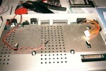
| 1 - Open your Atari and remove
the keyboard so that you'll have more room to work.
|
|
| 2 - along with your sio2ide
interface you were supplied a connector (which will be
connected to SIO_IO on the interface) , have some wires
cut (avoid to make them too short or you may have some
problem when connecting that cable to the sio2pc
interface, see step 3 for the different soldering
options before cutting the wires) and use you plier or a
crimping tool to have the wires tightened on the small
metal tabs. But don't slide the wires+metal tabs in the
connector yet... |
|
|
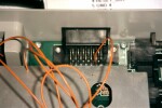
3
- Concerning the length of the wires you have two
options:
- either you have the wired
directly soldered on the top of sio port (on the pins
of the port), then you'll need something like 10cm
wires (to have some liberty to move around) (see
pictures )
- or you can solder those wires
on the solder side of your atari motherboard (you will
then need more wire length in order to have the wires
running from under the motherboard to the sio2ide
interface). It you prefer this option, it means you
have then to:
- remove the metal shielding
(use a plier to bend the metal clips)
- unscrew the motherboard
- then find the sio port
solder pads
I chose the quick and dirty
pin-soldering option (see pictures).
Solder the wires on the atari SIO port pins #3, 5, 7,
4, 10. Check twice before soldering (pin 1 is easy to
find since 1 is written on the motherboard but if you
have doubts look at the picture for pin number
identification).
[Note: beware if you chose the
motherboard solder side option the numbers will be
reversed, check twice before soldering]
[Note: I always check if the
solder joints are good with a multimeter to avoid
surprises later]
|
|
|
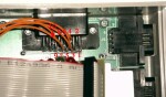
4
- Now you can slide the wires+metal tabs in the
connector matching the table below:
| SIO-IO pin |
SIGNAL |
ATARI SIO pin |
| 1 (see note 1) |
DATA_IN |
5 |
| 2 |
DATA_OUT |
3 |
| 3 |
COMMAND |
7 |
| 4 |
RESET_OUT |
- (see note 2) |
| 5 |
GND 4 |
(see note 3) |
| 6 |
GND |
4 |
| 7 |
VCC |
10 |
[Note 1: SIO-IO pin #1 is to be
found on the left of the connector and you can see it
written on the sio2ide interface if you look
closely]
[Note 2: the RESET_OUT signal is optional,
it works without connecting it]
[Note 3: I chose to
have a jumper from SIO-IO #5 and #6 and thus only one
wire on the SIO pin #4, if you prefer to keep the
original pinout then solder one more wire to SIO pin #4]
|
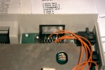 |
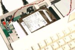
5 - Now you have to find +5v
and GND for the harddrive.
Don't
do what I did on the picture: I found an easy way
to have +5v and GND, I soldered the two wires on the
atari power supply socket but I didn't realize that
doing this would automatically bypass the atari on/off
switch. Thus when I plug the atari's power supply the
harddrive begins to spin automatically even if the atari
isn't switched ON. That's a very bad idea, find another
place to solder those two wires... |
 |
| 6 - ok everything is
soldered... |
 |
|
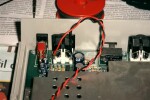
7
- now connect the small SIO cable to the SIO-IO
connector of the interface, connect the power supply to
the harddrive, the harddrive to the interface (see the
picture for the red-pin1 stuff), and voila...
[Note: you may have to find a way
to isolate the harddrive and the interface in order to
avoid shortcuts, I used paper for testing purposes but
something better is easy to find and is highly
necessary). |
 |
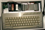
8 - Put the keyboard you will
need it to configure everything... ;)
But don't put
the cover back yet since we will have to access the
jumper settings. |
 |
> SIO2IDE
ConfigurationOnce the interface, solders and wires
are ok we have to configure the harddrive to work with the
sio2ide interface... Hook up your atari, disk drive and TV but
do not switch it on...
Some useful information:
Interface state monitor LEDs:
- PWR_LED - indicates the interface power supply status
- SIO_LED - indicates that the SIO command is received
- BSY_LED - indicates that the Hard Disk is busy or that
an error occured
- IDE_LED - indicates the IDE bus activity (HDD output)
| 1 - Before switching on your
atari set the SIO2IDE jumpers:
| Jumper |
Setting |
Description |
| ------------------------------------ |
| HD1_ZW |
Off |
Disk D1: Off |
| INIT_ZW |
On |
Disk swap D1<=>D2 |
| MS_ZW |
On |
Master mode |
[Note: you should have received
your SIO2IDE interface with this jumper setting]
|
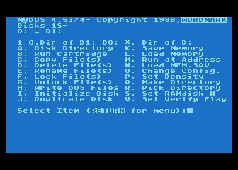
| 2 - Now insert your Mydos +
Fdisk floppy in the 1050 |
| 3 - Switch on your atari
while holding down the OPTION key to boot Mydos... After
some LED activity you should see Mydos menu and the
BSY_LED should NOT be active. If that's the case
everything is OK. If not check that all your connections
are ok and that you set the jumpers the proper way. |
|
|
4 - At the prompt type
L
then:
FDISK.COM
and
then Fdisk.com will be loaded (it is the sio2ide
configuration program)...
|
|
5 - On the first menu screen
type 1 to see the master SIO2IDE interface configuration
(you can have 2 sio2ide interfaces in your atari). You
will then have this menu:
1 - View Disks and SIO2IDE parameters
2 - View
Partition Table
3 - View Disks Sequence
4 -
Edit Partition Table
5 - Edit Disks Sequence
6
- Exit
Enter 2 to see the partition table.
You
will then see the 16 partitions (P1->P16) of the
harddrive. Sio2ide 1.0 is limited to 16 partitions with
a maximum of 65535 sectors per partition (it depends of
course on the hardrive, I did it with a small capacity
harddrive and I only had 8 partitions). But even with a
16 partitions harddisk sio2Ide 1.0 will see the
partitions 8 by 8 because they are associated to
disks and DOSes are limited to eight disks. With
the edit disk sequence screen you will be able to
access the other partitions by remapping/associating
them with different disks. But for the moment,
write down on a paper the number of sectors per
partition you will need it later on...
Now you can
exit Fdisk: press a key then enter 6 and
finally 3.
Your computer should now go back to
Mydos screen... |
|
6 - You must then change the
config of the dos (to tell him the number and the size
of the disks to be used)...
At the prompt enter :
O
Drive Number or Return: 2
Remove
Drive: N
Is Drive Configurable:
Y
High Capacity Drive: Y
Drive Size
(in sectors): [Note: enter here the
number of sectors for the Disk/Partition P2, ex:]
65535
Then we must initialize this Disk/Partition
(=format), so enter I at the prompt and
then:
Disk to Format: 2
Type (Y) to format
Drive 2: Y
You will have to repeat step 6 with every
drive from D3 to D8 (D2 is done now and you can't access
D9-D16 for the time being). Just replace 2 with
the number of your disk and of course the size in
sectors (that's why you had to write them down)
|
|
7 - you must not forget the
boot partition...
In fact we have now prepared
partition 2 to 8, but the interface must boot on a DOS
partition. You have then to prepare the partition #1 to
become the boot partition...
At the prompt enter
L then enter
FDISK.COM
Enter 1 to view
the master sio2ide settings
then enter 4 (edit
disk sequence)
enter 1 to edit one
disk
enter the disk: 2 (disk that you want to
modify)
enter the partition: 1 (you want to
associate partition 1 to disk 2 to access to the content
of the partition 1 when requesting Drive 2 under the
DOS)
then enter 2 to save the changes, enter
3, 6 and 3 to return to the DOS
screen.
Then repeat step 6 with Drive 2 (but
it will physically alter partition 1)...
after drive
2/partition 1 has been "O" + "I" you need to make it a
system/boot drive/partition by copying the DOS on it,
enter H, then 2.
Once the dos files are copied you may also want to
copy FDISK on this drive to access is easily from
the harddrive (use C under the dos).
[Note: now you can also repeat
step 6 with partitions P9 to P16 by associating
them to D2 to D8 with the Edit disk sequence of
FDISK... I won't describe it here since it's always
the same thing]
|
|
8 - Before trying your new
atari + harddrive you must then get the things back to
the normal (P1->D1, P2->D2) so launch FDISK.COM
enter:
L
FDISK.COM
1
4
and here
associate D1 to P1, and D2 to P2. Save your changes by
entering 2 and exit FDISK.
You can now switch off your computer...
|
|
|
9 - set SIO2IDE jumpers
| Jumper |
Setting |
Description |
| ------------------------------------ |
| HD1_ZW |
Off |
Disk D1: Off |
| INIT_ZW |
On |
Disk swap D1<=>D2 |
| MS_ZW |
On |
Master mode |
|
|
10 - Detach your 1050 disk
drive, switch on the computer and wait for Atari and HDD
power-up...
The computer will then start in basic
mode and only the PWR_LED on the SIO2IDE is
active
From the Atari BASIC prompt type BYE
command, you will then see the self test screen
Press
RESET key to restart the computer and load the
DOS from the SIO2IDE disk (D1:)
You should now have
the DOS screen (if you still have basic type DOS
and if no result check taht you've followed the steps
carefully)... Once at the dos prompt, you can run
FDISK.COM to change your configuration and access other
partitions...
[Note: if you want an automatic
system start without to start in basic and then pressing
Reset you must connect the Reset_Out signal (SIO_IO pin
4) as shown in the schematics in the Polish Technical
Manual...]
|
|
Here you are. Enjoy...
> Postface
having a harddrive is cool but you would prefer to have
your partitions full of games and utilities. There are 3 ways
of doing that:
- copy the files on floppies with your PC (special
equipment needed I will explain this method soon)
- use SIO2PC. That would be really the best choice since
all the files are on your PC and it's pretty fast and
easy...
- in fact the third way is not really a third option.
Either way 1 or 2 is long, so forget sio2ide 1.0 and upgrade
to sio2ide 3.0. It's not the same software, it's not the
same interface (the chip is not the same and some mods have
to be done on the interface) but with the 3.0 version here
is what you have:
ATARI side:
- uses standard Atari SIO at a speed of 19200 baud
- emulates Atari disks D1: to D7:
- can be used with any Atari DOS and OS
- can be used without any problems with other SIO
devices (disk drivers, printers, modems, SIO2PC, second
SIO2IDE etc)
- can be easy installed inside your Atari with 2.5'
laptop HD
- is easy to configure via special fdisk.com utility
software (changing disks sequence and active directory)
IDE device side:
- all IDE ATA/ATAPI devices can be used: Disk Drives
(2.5' and 3.5'), CD-ROMs, Compact Flash cards etc.
- supports PC file systems, FAT16 and FAT32
- supports CD file system, ISO9660
- supports ATR disk images (SD, DD up to 16MB)
- supports directory change (multiconfig)
- is easy to configure, many text configuration files
(sio2ide.cfg) can be stored in different directories
- disk configuration can be checked by special
checkfs.exe PC utility
- standard disk utilities can be used (defrag.exe,
scandisk.exe etc)
Let's also add that you can format your harddrive on your
PC, and you can also create your directories with all your
atari programs (such as ATR DD 16mo for example) from your PC.
Once done you just have to put back the harddrive in your
atari 130xe.
____________________________
Article written by Romual
Liné <romualdl@hotmail.com> |