A tari - K
eyboard - I nterface
Connect a PC-Keyboard to your ATARI 800/130!
-
all common PC Keyboards (MF2 Standard) useable
-
99% ATARI-compatible
-
several keyboard layouts (languages)
-
simply to install, no tuning
-
ATARI keyboard can be used the same time
-
macro memory for up to 60 keystrokes, will be hold after power off
-
AKI software can be updated
New professional manufactured board now available
!
-
No more soldering on the POKEY (only if POKEY is
socketed)
-
passive components in SMD package
-
no small SMDs, so it can be soldered by hand
-
it can be placed inside the shield
-
most connections are plugable, only 5 soldering points
-
socket for optinally macro EEPROM (up to 8KByte)
Sorry for my bad english, if theres somebody who can help me with a better
translation contact me !!! MacFalkner@aol.com |
 |
1. some short infos
AKI is a small interface platine to connect the ATARI 800/130 with every
common PC-AT-keyboard (also Windows 95 keyboards). The old ATARI keyboard
will be useable the same time. The AKI interface and the 5c DIN connector
/ or PS2 connector are build inside the ATARI. Its simple to build in cause
there is only a small soldering work to do. The interface is placed 'up-packed'
to the ATARI keyboard chip (POKEY), therefore the connection is very solid.
AKI is 99% softwarecompatible cause it is simply parallel switched to the
old keyboard. The POKEY chip will not be able to detect differences in
the signals. The compact layout allows to put the interface direct up to
the POKEY (ca. 25x50mm). The AKI CPU can be updated with new firmware*
* The PIC must be placed into an PIC programmer device, also programming
software will be required.
 |
 |
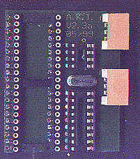
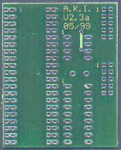
| AKI component side (new layout) |
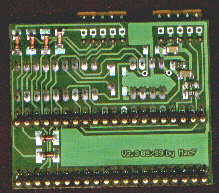
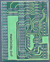
AKI soldering side (new layout) |
 |
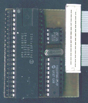 |
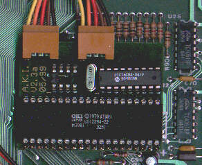
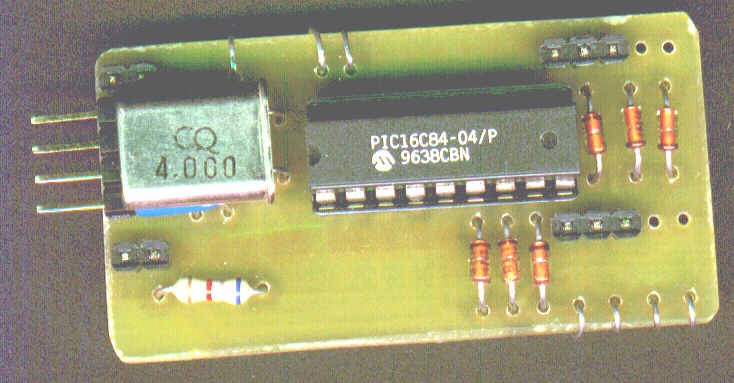
| One of the first tries of the AKI hardware :-) |
handmande board of the new layout with POKEY, EEPROM and PIC. Some
SMDs are on the soldering layer |
2. Build in
First, before you start, you will need an PC-keyboard. They are very
cheep this time, its no problem. Who wants to use an ergonomic cherry keyboard
can do this also :-). Look for 101/102 keys and MF2 standard. 5p DIN and
PS2 can be connected. All keyboards common this time, do this !!! Newbies
better use the DIN connector cause the PS2 is more difficully to sold.
All work should be done when the ATARI is switched off. Also a basic
electronic tool set should be availaible (theres no need of an oscilloscope
etc.).
Now follow the steps:
  |
Open the ATARI, put a hole for the connector. The connectors should
be placed from outside, then you will have no problems with the fixing
holes. A solid mechanical connection will be recommended. There isnt an
exact position giving for the connector. Everybody can choose its own place.
You should use short cable connections to the AKI. Lengths under 50cm are
uncritical. Attention! A longer shortcut of the power supply can be bad
for the ATARI-supply unit, a longer swap of the power supply lines will
be bad for the AKI CPU (PIC) and can kill the PC keyboard. A swapping of
the datalines will have no destroying effect (normally :-)). |
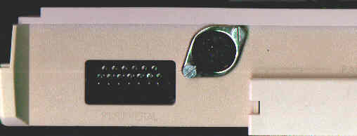
The figure shows the insertation of an 5p DIN connector in the ATARI 800XL.
Its placed between the SIO connector and the bus expansion port.
|
The AKI interface is placed 'up packed' to the POKEY chip (10 soldering
positions).It will be nice to have an ATARI with sockets for the chips
!!! Place out the POKEY, sold on the AKI and place the POKEY back. If your
POKEY have no carrier are there 3 variants: The first one, you sold the
AKI direkt onto the PIC, this is something complicated cause theres not
much space to sold. The second is you place a socket for the POKEY, but
this is much work and should only be done from professionals. The third
version is you sold an 40p carrier up to the PIC an plug the AKI inside.
In this case you must put a hole in the ground shield (the ATARI can also
work without the shield, but there can be reduced video picture quality).
Eventually, an capacitor, right under the POKEY must be layed down. |
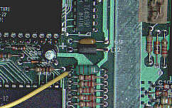
Insertation of the first prototype in the ATARI 800XL.
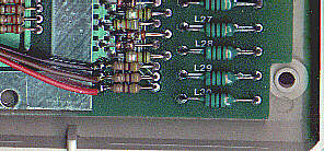
Connecton of START, SELECT and OPTION in an ATARI 800 XL (the 3 resistors
are right down outside the ground shield).
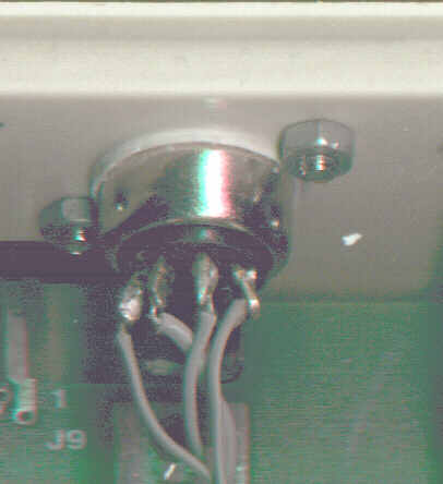
Connecting RESET line (gn / wh), right under the AKI.
| Signal definition |
ATARI 800XL / 130XE |
| START |
left side from R134 |
| SELECT |
left side from R135 |
| OPTION |
left side from R136 |
| RESET |
left side from L14 |
Now, also a connection to a switchable RAM-Disc can be done. This can
not be specified without knowing of the inserted RAM-Disc technology, see
section "AKI and RAM Extensions" for more details.
Now turn on your ATARI, test the function of the old ATARI keyboard.
If it works, plug in the PC keyboard and start ... You can start the ATARI
build in keyboard test, but this will not be a good indicator to test the
PC keyboard. If only one key dont work, the defect is placed in the PC
keyboard. If nothing works the whole installation must be checked. Latest,
after plug out the PIC of the AKI, the old ATARI keyboard must work.
Some tips for troubleshooting:
-
First: on a selfmade platine all connections must be tested for micro
breaks and bridges. Check the polarity of the diodes!
The 'nose' of the PIC must be placed in direction to the keyboard
connector!
-
Check the supply voltage direct between PIN5 (GND) and PIN14(+5V),
there must be 5V +-10%, is this wrong check the connections to the POKEY
-
On the keyboard connector also 5V must be measureabled. On the PC keyboard,
after switch on, the three lamps should flash on (PC keyboard selftest).
If the supply is ok. and theres no flashing, the PC keyboard is defect
or a very old one.
-
Check with a logictester on RESET PIN4. There must be a hi, if not check
R1 and C1 for bad connections.
-
On PIN 15 (16) must be pulses (2 / 4 MHz), if not, check the crystal
and
PIC
CPU (is the PIC correct programmed ?).
-
On PIN 12 and 13 must be frequences with 31KHz and 500Hz, if not test the
connections
to the POKEY.
-
On a keypressing on the PC keyboard, on PIN 2 and 3 must be a pulse raster,
also on output PINS 10 and 11, if not check the datalines to the keyboard
(CLK and DATA swapped ???, is the PIC correct programmed,
PIC defect, polarity of diodes correct?)
-
On pressing F5, F6, F7, F8 (also SHIFT-F8) on PIC pins 6,7,8,9,17 a static
low must appear, on PIN 17 (only RAMDISC) the signal must change after
RESET / SH-RESET (is the PIC correct programmed ?)
-
Now check for the same signals on (START, SELCT, OPTION, RESET), if theres
no signal, check diodes and its polarity.
3. Keyboardlayout
fig. 8: PC-MF2-standardkeyboard (english Version, keys 42 and 45 added
on german layout)
The PC-keyboardlayout is mostly identic with the printed symbols on
the keys with the german / english (american) keyboard. The english layout
is mostly common with the original ATARI layout, maybe some german PC users
prefer her layout.
Keynumbers with several language functions: 3,7,8,9,10,11,12,13,22,27,28,40,41,42,45,46,53,54,55.
Here are the special funtioin keys:
| PC key |
ATARI-Emulation |
| CTRL-ALT-DEL |
RESET |
| F1 |
ATARI (1200er) F1 key* , also SHIFT / CTRL |
| F2 |
ATARI (1200er) F2 key* , also SHIFT / CTRL |
| F3 |
ATARI (1200er) F3 key* , also SHIFT / CTRL |
| F4 |
ATARI (1200er) F4 key* , also SHIFT / CTRL |
| F5 |
START |
| F6 |
SELECT |
| F7 |
OPTION |
| F8 |
RESET |
| F9 |
free |
| F10 |
HELP |
| F11 |
INVERS |
| F12 |
BREAK |
| ALT-F9 |
sending macro 1 |
| ALT-F10 |
sending macro 2 |
| ALT-F11 |
sending macro 3 |
| ALT-F12 |
sending macro 4 |
| CTRL-ALT-F9 |
recording macro 1 (max. 15 keystrokes) |
| CTRL-ALT-F10 |
recording macro 2 (max. 15 keystrokes) |
| CTRL-ALT-F11 |
recording macro 3 (max. 15 keystrokes) |
| CTRL-ALT-F12 |
recording macro 4 (max. 15 keystrokes) |
| ALT-F1 |
sending AKI versionnumber |
| ALT-F2 |
sending fixed macro POKE (for a faster keyboard in BASIC) |
| ALT-F3 |
switching between german and english keyboard layout (stays after power
off) |
| ALT-F4 |
stop macro recording |
* there are some ATARI models wich have keys F1...F4. These keys are
supported from the ATARI OS (also 800/130er OS!) and have following functions:
| F1 |
Cursor up |
| F2 |
Cursor down |
| F3 |
Cursor left |
| F4 |
Cursor right |
| SHIFT-F1 |
goto top of screen (HOME) |
| SHIFT-F2 |
goto end of line |
| SHIFT-F3 |
goto start of line |
| SHIFT-F4 |
goto bottom of screen |
| CTRL-F1 |
switchs off keyboard until pressing CTRL-F1 (Attention trap!!!) |
| CTRL-F2 |
switchs off screen until pressing any key |
| CTRL-F3 |
toggles keyboardclick |
| CTRL-F4 |
toggles charset (graphic / international) |
4. Softwarecompatibility
Like said above, AKI is 99% softwarecompatible, cause the ATARI is not
able to detect differences to the original keyboard. Here are some differences
(the 1 percent):
-
The keys START, SELECT, OPTION, RESET, also BREAK, SHIFT and CONTROL, are
sampled in combination from the atari. A standard PC keyboard cant sample
combination codes*. Pressing more then one of these keys at the same time,
under several circumstances can't be detected. The AKI user will not be
able to press START, SELECT, OPTION and RESET at the same time (F5, F6,
F7, F8). On a tested FUJITSU N860-8725-T853 and a NCR H0150-STD1-12, START,
OPTION and RESET can't be pressed at the same time (is there anybody working
with cassette drive and an AKI ?). Combinations from not more then 2 keys
are working correctly. For other crazy keystrokes use the ATARI keyboard.
Im not sure that the 100% compatible TRANSKEY can handle these situations
:-).
-
Through the several language keyboardlayouts it can be that some chars
are not reachable. Mainly this is important for users of the german layout
and an english keyboard hardware. On the english hardware the key 45 is
not present, therefore a '|' cant be reached under german softwarelayout.
Other problems can occur on other hardware/software combinations.
* If it comes to a ghosting effect (the keyboard controller detects keys
that are not stroked) through pressing more than two keys at the same time,
the keys they are first scanned (in matrix order!) are guilty. This can
be readed in the technical documents for the keyboards.
-
Keyboard macros are sended by the AKI. In the actual version the sending
speed is not configureable, it can be that slow ATARI programs ignore some
keystrokes sended by macros. The macro sending speed is tested in the standard
BASIC there its ok. Perhaps in a new software version, there is the option
to change macro sending speed.
Another interesting effect is occuring when two keys are pressed very quick.
The ATARI-OS is not able to detect 2 several keys in 100ms. Now with an
new keyboard you can press the keys quicker, therefore it can be that some
strokes are ignored. (for instance LDA > LA or STA > SA). Now AKI software
caches 2 keystrokes, so this effect will be reduced.
5. AKI and RAM-Expansions
There is an output on the AKI interface, especially designed to switch
RAM-Disc systems with a bank switching option. The 2 ATARI switching is
very easy with the AKI. Press RESET for the first one, SH-RESET for the
second. The output is switched some time after activating the RESET signal,
so a sure switching is guaranteed. There are many several extensions for
the ATARI available, so i cant give an exact description, how to do. Mostly
the OS / RAM selection is done by an mechanical switch. The following methods
are common:
The AKI ouput has an so called 'open collector' therefore not all variants
are uncritical to connect. Variant "A" gives no problem, the AKI switching
output can be directly connected to the input of the extension (take care
that the resistor dimension is >1KOhm). Dont connect
to variant B or C, destroying the PIC can be result. If you
have variant B or C in your ATARI, rewire it to variant A, the switching
ability stays the same. Now you can contact your AKI output additianally.
6. Technical infos
The AKI is a one chip processor system with an PIC processor with 64
byte internal EEPROM. The hardware is mostly the standard application for
the PIC processor. The PIC is receiving the serial AT keyboard codes, interpreting
it and simulate an keystroke in the ATARI keyboard matrix. The SHIFT and
CONTROL keys are 1:1 software connected. The supply current is typical
20mA and the PC keyboard needs 70mA-160mA, and its no problem for the ATARI
power supply.
Schematic (GIF, 30KByte, 300dpi)
Layout (GIF, 12KByte, 300dpi), new
SMD Layout (GIF, 20KByte, 300dpi)
Hexfile for PIC-Programming, actual Version! (Intellec8,
6KByte)
The following components are needed:
-
a programmed PIC in a DIL package (4MHz version), a socket will be recommended
for updates
-
6 small signal diodes, for instance 1N4148
-
1 crystal (approx. 4MHz)
-
R1 resistor 100KOhm
-
R2 resistor 2,2 ... 10KOhm
-
C1 capacitor 100nF
-
4 p PF connector, 2.54 mm (1/10")
-
1 platine
Some infos for the insider (sorry, only in german this time):
Funktionsweise von AKI, Matrixcodes (Scancodes)
der ATARI-Tastatur ... u.v.m ! (TXT, 7KByte)
Liste mit allen bisher durchgeführten Änderungen
(Bugreport) !
7. Selling, Handling, Quality and further development
This is a hobby project of mine, that is free availaible for all ATARI
freaks. This document and all linked files are F
r e e w a r e and can be copied free or for a selfcost price.
The copying of CAD and assembler sourcefiles is n
o t a l l o w e d . Reproducing the hardware is
free for single boards for private/friends. The reproducing for commercial
is n o t a l l o
w e d .
Please contact me for availability / delivery outside germany
MacFalkner@aol.com
| AKI complete and tested, incl. all wires and plugs |
 |
30,- Euro/US$* |
| AKI PIC programmed with the newest software version |
|
15,- Euro/US$* |
| AKI board (empty), double sided, solderstopmask |
  |
15,- Euro/US$* |
* all prices without P+S.
I will be enjoyed for tips to upgrade the PIC software or reported bugs,
or contact me if you have some questions: MacFalkner@aol.com
Sources:
-
SAMS computerfacts (ATARI schematics), copies from ABBUC-Bauplanservice,
ABBUC-HOME
-
Der ATARI mit IBM-Tastatur (TRANSKEY), copies from ABBUC-Bauplanservice,
ABBUC-HOME
-
PC-Tastatur am ATARI XL (description of the ATARI matrixcodes), copie from
ABBUC-Bauplanservice, ABBUC-HOME
-
National Semiconductor: Application Note 734: 'MF2 Compatible Keyboard
With COP8 Microcontrollers', NS-HOME
-
Motorola: Application Note 1723: 'Interfacing MC68HC05 Microcontrollers
to the IBM AT Keyboard Interface', MOTOROLA-SEMICONDUCTOR-HOME
-
PIC16C84 from Microchip, MICROCHIP-HOME
Many thanks to:
-
Burkhard Rau (Media-Inside) for beta test and Nörgeln,
-
the A.B.B.U.C. - Bauplanservice for the technical documents,
-
Erhard 'Floppy-Doc' Pütz for the betatest, the infos about TRANSKEY,
and the inspiration to make this side!.
11.10.1998 / 05/1999, André Bertram. MacFalkner@aol.com