EVERYTHING YOU WANTED TO KNOW ABOUT
YOUR ATARI BUT WERE AFRAID TO ASK (PART 1)
We are pleased to welcome John J. Smith to our pages with a regular column on hardware. John's articles will feature a mixture of hard facts, ideas and projects. You will be shown inside the 800 and find out what is inside a cartridge among many other things in future Hard(ware) Facts.
JOYSTICK PORTS
The first thing most people seem to want to know is what you can plug into the
I/0 ports on the front of the Atari 800. The answer Is many things but in order to do so, especially if you build something yourself, you will need to know what the pin connections are. Figure 1 shows the pin connections of port 1 and the remaining ports are the same. It is important to note that the connections shown are exactly as you see them when sitting in front of the computer. The connections on the computer are plugs with pins (male) and if you want to connect something you will need female sockets. These are called 9 way D type connectors and manufacturers seem to call them
DB9S connectors. You will most probably get them from your local shop, if you have one, or by mail order and everyone seems to have their own part numbers. One source of supply is Maplin Electronics, P.O.Box 3, Rayleigh, Essex and their part number for the 9 way sockets is RK61R.
I suggest that you also use covers to hide the wires and solder connections and the Maplin part number is RK 62S. These are sometimes known as 'hoods'.

Figure 1 - controller port connections
Pin 1 Joystick - forward
Pin 2 Joystick - back
Pin 3 Joystick - left
Pin 4 Joystick - right
Pin 5 B paddle (potentiometer) input
Pin 6 Trigger input
Pin 7 5 volts available
Pin 8 Ground (Earth)
Pin 9 A paddle (potentiometer) input
Now that you know what the I/0 port connections are maybe you want to build something to plug in. Let's start with something simple as even
I have not yet figured out how to build a trackball! When I do I will let you have details. How about a joystick? At first this seems a good idea but if you are a real beginner, even this can be a challenge as you have to get the lever to pivot in all directions without failing apart. No, for your first project
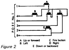
I would suggest a simple push-button cursor control to provide similar controls to a joystick i.e. Up, Down, Left, Right and Fire. Five
separate push buttons are required and the wiring diagram for these is shown in Figure 2.

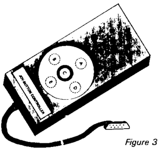
Note that pin 8 is common to all five push buttons and that pins 5,7 & 9 are unused so that you only need a six way cable for wiring. One possible suggestion for mounting is to use a small handy sized box and mount the buttons as shown in figure 3. A plastic ring can cover buttons A B, D and E so that a rocking action can be used. How you achieve the final design is up to you!

|
ATARI PORT 3 Pin No.
|
MX80 /PRINTER Pin Na
|
ALSO KNOWN AS
|
|
1
|
2
|
DATA 1 LINE
|
|
2
|
3
|
DATA 2 LINE
|
|
3
|
4
|
DATA 3 LINE
|
|
4
|
5
|
DATA 4 LINE
|
|
6
|
9
|
DATA 8 LINE
|
|
8
|
19 to 29 inclusive
|
GROUND
|
|
ATARI PORT 4 Pin No.
|
MX80 PRINTER Pin No.
|
ALSO KNOWN AS
|
|
1
|
6
|
DATA 5 LINE
|
|
2
|
7
|
DATA 6 LINE
|
|
3
|
8
|
DATA 7 LINE
|
|
4
|
1
|
STROBE
|
|
6
|
11
|
BUSY
|
|
8
|
19 to 29 inclusive
|
GROUND
|
Figure 4 - MX80 connection
A PRINTER
CONNECTION
Most people think that these 9 pin controller ports can only be used with joysticks and paddles. Not so! For instance if you want to connect a printer, say an Epson MX80 which has a Centronics interface, this can be connected to ports 3 and 4 as shown in Figure 4. To protect the Atari, it is suggested that transistors be connected to each of the ten wires going to it. All you have to do is connect the base to Atari, collector to ground and emitter to MX80 using PNP transistors 2N2907A.
I know that there are more than 10 wires but you do not have to protect the ground wires. Figure 5 shows the transistor for those of you who do not know their emitter from their elbow.

For ease of construction a Veroboard is suggested and with the tracks cut in the right place this gives a fairly neat layout but a printed circuit is to be preferred. Again actual construction space is left to the individual due to lack of space in this column.
Finally the bad news! You will have to write your own software to drive the printer or it will just sit there and do nothing. With all you software experts out there, it should not prove too difficult and when you have written a suitable program please let PAGE 6 know about it.
A BETTER PICTURE?
It seems that some people may have a colour TV which does not give an entirely correct colour as produced by the Atari. If you are happy with the normal TV picture but not with the colour produced by the computer make sure firstly that the channel used by the computer is properly fine-tuned. If you are still not happy then you may adjust R309 on the Atari - the 'colour adjustment potentiometer'. The trick is finding it! This control is accessible by removing the top plastic cover of the machine revealing the large metal diecast cover into which the RAMs/ROMs are plugged. Looking at the computer from the back, i.e. with the keyboard away from you, there is a small hole at the upper right hand side on the rear of the diecast block. You can access R309 with a small insulated screwdriver through this hole. As the control is pre-set by the factory it should be O.K. with most TV's so if you are
already getting a good picture do not fiddle, you will only make things worse. If your
picture is bad, what can you lose? Please remember though to adjust the TV first before suspecting the computer.

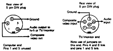
If you are fortunate enough to have one of those TV sets with a 6 pin video socket, you can connect the Atari 800 directly to this instead of the aerial socket and get monitor quality.
If you have genuine monitor, you can also use this system and you can also have hi-fi sound!
Next issue - a look inside a cartridge and a look inside your 800.
top