AN ALTERNATIVE LIGHT PEN
I believe it was Marconi
who said that invention is 1% inspiration and 99% perspiration. To
relieve some of the hard work in trying to get a recognisable graphics
image on the screen, I needed some inspiration for something that would
be better than POKEs and DRAWTOs.
What about a light pen?
There are, after all, locations for it (54284 and 54285) but I could not
find one for the Atari, although rumour has it that the one for the
Apple might work. I could of course have built my own light pen but then
suddenly graphics tablets came along. Could this be the answer? Not at
£90 at time, at least not for me. I put on my thinking cap and came up
with the 1% inspiration for a minimum cost device in the hope that
someone could write the software and make it work with the Atari.
Although this particular version is untried, I did make a working
bar-decoder some six or seven years ago but there was little interest at
the time. Anyway this simplified version should enable you to produce
pictures on a screen.
This is no ordinary light
pen. Light pens react to the presence or absence of light from a
particular area of a CRT screen when drawing across the screen with the
pen. This idea is to place a drawing flat on a table and use the special
pen which has its own light source to manually scan across the page line
by line to detect light and dark areas of the image. This will produce
an equivalent electrical output along the wire to the computer and the
signal would be interpreted by software to produce an exact reproduction
on the CRT screen. The idea is shown in a simplified form but if you
have the time and a Meccano set or
something similar, you could perhaps produce a rotating drum around
which the picture is fitted. The drum would be fitted on to a threaded
rod and driven at constant speed! The pen would be fixed in position
vertically and moved horizontally to scan a different part of the
picture as the drum rotates. The result would be the same as scanning by
hand but would possibly be more accurate and faster.
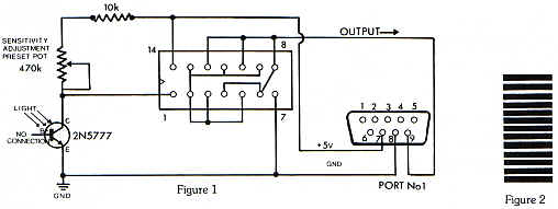
Due to limited space, I
will only describe the 'pen-reader'. The circuit diagram is quite simple
and the only tricky bit is getting the spacing right from the paper to
the lens. (Figure 1).
The preset pot used for
sensitivity adjustments is the type with a screwdriver slot and is best
set to midway and then adjusted after construction so that it reacts
properly during the transition from black to white. A PEEK at locations
54284 and 54285 would give the necessary reading. There is obviously
software needed for this but this should present no problems to PAGE 6
readers!
The light sensitive
transistor has three connections but the base (centre) connection is not
used. Looking at the flat side with pins pointing down the E (Emitter)
is on the left, B (Base) in the centre and C (Collector) on the right
The light sensitive part is that circular lens type part and must be
fitted so that the light reflected off the page, as seen through the
hole in the box, passes through the 8mm lens and falls on this spot on
the transistor. I would again emphasise that this particular version is
untried and it is probable that some hardware experts among the
readership will be inspired by this article to come up with a better
solution. If you do, please let me know. I want to try out your ideas!
The 'pen' used to read a drawing is
not really a pen at all but instead consists of a small box or other
suitable container approx. 4" x 2" x 1". It sounds a
little large but remember that it has to contain all the parts. These
are as follows.
Light
sensitive transistor 2N5777
Lens
- 8mm cine movie projector type.
Lamp
-1.5 volt or 1.1 volt torch bulb with lens cap on one end.
Battery
- 1.5 volt cell type HP7
Potentiometer
- 470K preset pot
Integrated
circuit - 74C04
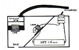
The
inside of the box should be painted matt black to prevent reflections.
The hole in the bottom of the box should be approximately 1/2"
from one end and the size of the hole approximately 1/8".
Size of the hole equals definition to sensitivity and should be adjusted
by experiment.
The lens has a threaded portion on the
outside allowing a certain amount of zooming enabling adjustment to be
made. This adjustment is critical and is best explained by using figure
2. When the lens is the correct distance from the page the black line
will fill the whole lens as magnification is quite powerful on this type
of lens. Moving it across the stripes will appear to make the lens
alternate from dark to light The distance from the page should be
measured and the transistor mounted behind the lens at equivalent
distance in its own light proof box looking down at the hole through
which the page is read. Make sure that the lamp is slightly behind and
to one side of the lens and positioned so that it is aimed at the hole.
A tall piece of plastic or PCB will help.
There it is then, an idea for a cheap graphics device.
There you have the inspiration, can you provide the perspiration and
make it work?
top
