This article shows how to use any model of Atari
computer to measure temperature, using only one component, some wire
and a connector.
To use a computer to measure values in the real
world we need a way of converting analogue values, such as
temperature, light, or resistance into digital or on/off signals
which the computer's chips can deal with. Luckily Atari computers
have several analogue to digital converters built in to handle the
paddle controllers, two per joystick port. Paddles, which are simply
variable resistors, are not the only devices that can be plugged in
however, the resistance of any device can be measured and usable
values are 1k ohm to 500k ohms.
IT COULDN'T BE EASIER!
Thermistors are readily available devices whose
resistance varies with temperature. All that is needed is to wire up
a thermistor to two pins of a suitable connector, plug it into a
joystick port and with a few lines of BASIC your Atari will be
measuring temperature.
We need to choose a thermistor that has a suitable
resistance in the temperature range we are interested in. Type VA
1067S is a good choice as it has a resistance of 150k ohms at 25
degrees centigrade.
The parts required are available from Maplin
Electronic Supplies, P.O. Box 3, Rayleigh, Essex SS6 2BR.
Thermistor
VA 1067S Order code FX43W 78 pence
D-Range 9
way socket Order code RK61R 95 pence
MAKING THE RIGHT CONNECTIONS
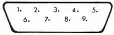
Joystick port
1.
Joystick switch - forward
2. Joystick switch - back
3. Joystick switch - left / Paddle A trigger
4.
Joystick switch - right/ Paddle B trigger
5. Paddle
B
6. Joystick trigger
7. +5V
8. 0V
9. Paddle A
The thermistor should be connected by suitable lengths of wire to
pins 7 and 9 of the connector. These will be numbered on the socket
but you need excellent eyesight or a magnifying glass to see them.
The value will be read from BASIC from PADDLE(0) when plugged into
joystick port 1 or PADDLE(2) in port 2. These values will vary from
1, at minimum resistance, to a maximum of 228.
A second
thermistor could be connected to pins 5 and 7 and read as PADDLE(1)
or PADDLE(3). In fact an Atari 400 or 800 could have up to eight
analogue inputs and Atari 600XL, 800XL and 1200XL models up to four.
A DEGREE OF SUCCESS
So far so good, that's the hardware done, now for
the software. Our computerised thermometer must be calibrated. Plug
it into controller port 2 (then you won't need to unplug your
joystick), and enter and run the following one line program:
10 PRINT PADDLE(2):GOTO 10
Next, put the thermistor in a cool place along
with a thermometer, centigrade or Fahrenheit, whichever scale you
wish your program to use. After a few minutes, when readings have
stabilised, note the thermometer reading and the paddle value. Give
these values to variables LOTEMP and LOPADDLE. Move the thermistor
and thermometer to a warm place and repeat the procedure, giving
values to HITEMP and HIPADDLE. The device has a negative temperature
coefficient so that when the temperature rises the resistance and
paddle value fall. These four variables are used to calculate the
change in resistance per degree, which is stored in the variable
FACTOR. See lines 1100 to 1130 of listing 1. The above variables are
used in the conversion subroutine shown in listing 1 at line 5000.
Reading the temperature in your own programs is
very easy. You simply need to get the value of PADDLE(2), and change
it to degrees centigrade with the conversion subroutine. The program
in listing 1 does this and continuously displays both the paddle
value and temperature on the screen. Hopefully you can think of a
more imaginative application.
As mentioned earlier any device with a variable
resistance may be used, and another very simple project is to
connect up a light dependant resistor (LDR). This could then be
used, for example, to detect the breaking of a beam of light falling
on the LDR and then sounding an alarm, or to count objects passing
in front of it.
top