Many home computer packages exist that enable the
user to draw 3-D images on the screen, however these are usually
only simple 'wire-frame' drawings and do not provide much realism.
Solid Modelling will enable the user to draw solid 3-D images with
correct shading according to a given light source and also provide a
variety of surface textures. The images are drawn by combining basic
shapes (or portions of them) into the shape required. The technique
of combining basic shapes makes the construction of complex objects
extremely easy and quick without the need for the user to have any
great artistic ability. The program also provides for the storage of
the drawings on disk.
DRAWING WITH SOLID MODELLING
The whole screen is used for drawing and is in
Graphics 8 Mode to provide the highest possible resolution (320 x
192). Very few on screen prompts are given while a drawing is being
developed. This is done so that the drawing can be as large as
possible and it also enables an experienced user to develop the
drawing very quickly.
BASIC SHAPES
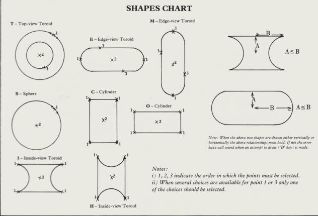
The shapes available in SOLID MODELLING are shown
in the accompanying chart. By using only parts of the basic shapes
(clipping) quite complex drawings can be made. The following steps
are required to draw a basic shape (or part of it).
1) Press the key that denotes the required shape,
e.g. 'S' for Sphere. A small single pixel cursor will appear which
can be moved around the screen by the joystick.
2) Select the necessary number of points to define
the required shape by pressing the joystick fire button when the
cursor is in the required position on the screen. A short beep will
indicate the point has been selected. The Sphere, Cylinder and
Inside-View Toroid require two points to define them, while the
Top-View and Edge-View Toroids require three. Refer to the 'Shapes
Chart' for details. The cursor will disappear when all the required
points have been selected.
3) This step is optional and allows the shape to
be 'clipped' so that only a portion of it is drawn. It is important
to understand that clipping is relative to the centre of the shape
(always the second selected point). A shape can be clipped in up to
four directions, right of centre, left of centre, above centre or
below centre. When a shape is clipped only the part of the shape
from the centre to 'clip-line' will be drawn. The clip-line for
right and left of centre is a vertical line drawn through the
'clip-point' (see below), while the clip-line for above and below of
centre is a horizontal line drawn through clip-point. For each
direction of clipping define a clip-point as follows:
a) Press the appropriate 'arrow' key for the
direction required, e.g. Right Arrow for clipping right of centre.
The cursor will then appear.
b) Move the cursor (joystick) to the required screen position and
then select (fire button) the clip-point. A short beep will indicate
the clip-point has been selected. N.B. The clip-point will not be
displayed.
4) When the shape has been defined and optionally
clipped the 'D' key must be pressed to actually draw the shape.
SPECIAL CURSOR POSITIONING
The 'X' and 'Y' keys provide a cursor control
function which is extremely useful for positioning basic shapes
relative to each other. They can be used during selection of the
points to define a shape. When either of these keys is pressed the
cursor will move halfway between its current position and the last
selected point. If the 'X' key is pressed the adjustment of the
cursor occurs on the X axis, and similarly on the Y axis if the 'Y'
key is used. For example, if you required to draw a sphere between
two vertical cylinders but with the Sphere touching each cylinder
this could be done as follows.
Select the first point required to define the
sphere by positioning the cursor on the edge of the first cylinder.
Move the cursor to the edge of the second cylinder and then press
the 'X' key . The cursor will now be at the centre of the required
sphere. Select this point and then press 'D' to draw the sphere.
Many
other similar uses can be found for these two keys.
GENERAL CONTROL KEYS
The functions of the drawing program are selected
by the pressing of the appropriate keys (e.g. 'S' to draw a sphere).
These keys will immediately take effect. A short beep signals the
pressing of a control key. If any error occurs during program
operation a longer low buzz will sound. Sometimes screen prompts
will occur and these must be responded to before any other function
can be started. The control keys that determine the lighting and
shading textures must be set prior to pressing 'D' to draw the
shape.
SHAPE CONTROL KEYS
One of the following keys must be selected before
a shape can be drawn.
T -
Top-View Toroid
S - Sphere
C - Cylinder (Vertical Axis)
O - Cylinder (Horizontal Axis)
E- Edge-View Toroid (Vertical Axis)
M - Edge-View Toroid (Horizontal Axis)
I -
Inside-View Toroid (Vertical Axis)
H - Inside-View Toroid (Horizontal Axis)
OTHER CONTROL KEYS
Lighting
1 - One light source.
2 - Two light sources i.e. shadows not so harsh.
3 - 3-D effect removed by direct light from front, however strength
of light source (shade) may be specified. The shade value can be
from 0 (white) to 64 (black).
Texture
N - Normal
half-tone
R - Random
Writing on the Drawing / Fast cursor
W - Enables text to be written to the drawing. The
cursor appears and should be moved (joystick) to the required
position and then selected (fire button). A prompt for up to 20
characters of text will then appear and the text will be written to
the screen. It will be noted that the cursor moves a character at a
time and is therefore much faster. This key can therefore be used as
a fast cursor option provided the fire button is not pressed prior
to the next required control key.
Saving and loading
A - Alters
the current filename to be used for filing and retrieving drawings.
A prompt for the new file name will appear and this will then be
used for any file or retrieval request. Remember to put the drive
identifier and colon ":" in front of the file name you require.
F - File
the drawing on the screen onto disk using the current filename (see
'A' above).
G - Get
the drawing from diskette onto the screen using the current filename
(see 'A' above).
Erasing
Q - Quit the current drawing, i.e. erase the
screen. A prompt will appear to check that you are sure! If you only
require to erase part of the drawing this can be done by drawing
over the unwanted part with a 'black' shape.
TYPING IT IN
Because of the combination of BASIC and machine
code routines which are read from disk by the Basic listing it is
important to type the programs in correctly. Follow these
instructions carefully.
1. Type in Listing 1 and SAVE with the filename
D:LOADER.3D. This program is not directly used by the main program
and is saved just as a precaution.
2. Make sure that you have a formatted disk in drive 1, then RUN the
program you have just saved. This will create two additional
programs on the disk, ASSEM1.3D and ASSEM2.3D.
3. Type in Listing 2 and SAVE it to the same disk with the filename
D:INTRO.3D.
4. Type in Listing 3 and SAVE it to the same disk with the filename
D:PROGRAM.3D.
RUNNING THE PROGRAM
1. Boot up the computer using DOS 2.0 or 2.5 and
type RUN "D:INTRO.3D".
2. When the Ready prompt appears type RUN "D:PROGRAM.3D"
3. If you have any problem, you must switch off before running
INTRO.3D again.
The program will load the machine code routines
from disk and then show 'PROGRAM LOADED' on screen. You are now ready to
start.
Listing 1
|
|
|
 |
Listing 2
|
|
|
|
Listing 3
|
|
|
|
SOLID MODELLING ON DISK
Disk subscribers will find a
slightly modified version of Solid Modelling on their issue
disk. This loads two title screens as the program is
initialising which give superb examples of what can be achieved.
The disk also contains four example drawings.
Issue 26 disk is also available
separately if required at £3.95.
top