A write protect modification for
810 disk drives
The purpose of this project is
to enhance the write-protect capabilities of the Atari 810 disk
drive. It will give you a switchable write protect tab so that you
can ensure the safety of data, make one-off file changes, or use
the B side of disks without cutting a hole.
To complete the modification you
need to be a very competent circuit builder. It is extremely easy
to make mistakes and just one slip-up could ruin your disk drive
and cost you over £60 for repair. If in doubt give up! Because of
this, I have not aimed to give step by step instructions, so if
you or a friend do not have such skills, I recommend you look at
the Autotect reviewed in PAGE 6 as an alternative.
Undertaking this product will render
the warranty of the 810 void. If you choose to do the alteration,
read this article all the way through first.
COMPONENTS REQUIRED
1 x Verostrip (Maplin FL17l)
2 x locking DPDT push switches
with single mounting bracket, screws, spacers and buttons. (Maplin
FH67X, FH75S& FL31J or Tandy 275-9401)
1 x Green LED with holder
1 x Red flashing (see text) LED
(Tandy 276-036) with holder
1 x packet of Veropins (Maplin
FL24B)
1 x 5-way socket (Maplin BH66W
& 5 x YW25C)
Wire (multicoloured)
2 x small right angle brackets
(Meccano?)
3 x bolts/nuts/washers
2 x knurled washers
There are some components worth
saying more about. Most important is the flashing red LED. Although
this will cost you about £1.10, ten times more than an ordinary
red LED, and a trip to Tandy is required (Maplin do not stock it)
it really is vital in order to keep your attention whilst write-enable
is on. Cut costs, and you could lose in the long term. Any LED holders
should do, but I don't recommend the chrome panel holders (Tandy
276-080, Maplin FM38R) because they cut the viewing angle too much.
A proper PCB plug {Maplin RK67X) could be used if you wish, but
I found Veropins quite satisfactory, and you need them anyway. Don't
cut the present cable or you will not be able to restore the 810
to its original state if you want to.
Although Maplin and Tandy have
been quoted as sources of supply, many of these components should
be available from your local electronics shop.
CONSTRUCTION
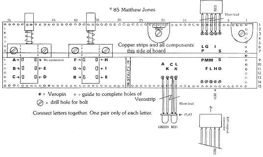
The diagrams should be sufficient
for anyone capable of building the modification, but here are some
hints you may find useful.
Make sure the 'veropin plug' is
not obstructed by wire ends around it (a file may be required),
or it may not 'make' properly and fall off later. Whatever plug
type you use, make sure only the marked wire is red, in order to
aid you in future. (The 810 pcb has the red wire marked).
I placed two LEDs next to the BUSY
and PWR ON LEDs, but you could put them anywhere. Holes will have
to be drilled to suit your holders.
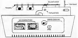
The 810 top, removed by taking
the four little discs at the top off to expose the screws, has to
be modified to expose the switches. If you look inside the top,
you will see moulded holes at the rear (opposites for the power
in and drive select switches). Cut out the two large round holes
with a sharp knife.
The switches themselves must be
mounted on the PCB using spacers. I used an old ballpoint pen barrel
cut at 7mm intervals. These are needed to position the switches
behind the holes. The switches are not soldered direct to the veroboard,
but wired together, i.e. A to A, B to B etc. There are only two
of each letter.
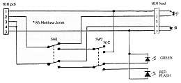
After you have built the board,
wired up the LEDs and connected the flying socket, you must spend
plenty of time checking your work. First, check that you have made
all the right connections as shown in the diagram. Second, very
carefully check that there are no solder splashes or strands of
wire that are, or may be in future, shorting two points. Terrible
damage can be caused by such shorts. Finally, repeat the two checks.
If you find anything wrong, correct it, and start the checks again.
You cannot be too careful.
Only when you have thoroughly checked
your work should you fit it to the 810. Once you have unplugged
the power lead, you have to locate plug number J101, which is at
the back on the vertical board, and note the position of the red
wire (also marked on the PCB). Gently remove the socket, (the plug
has the pins) and fit it onto the Veropin plug, ensuring the red
wire matches. Now connect your flying socket to J101, checking that
the red wire follows through all the way from J101 to the original
socket (ignoring the break on the Verostrip).
The two right angle brackets are
each used in different ways. You will find one hole suitable for
a bolt near the centre in the metal plate at the back of the 810.
The two knurled washers are to be used with this bracket to hold
it tightly in place without pivoting. The second bracket is used
to help prevent pivoting whilst the switches are operated. It will
rest inside the metal back plate to which the other bracket is bolted.
When mounted at the back, the new board should not interfere with
any drive components. If your drive is different, do not attempt
to fit this modification, as the circuits may have changed.
8-Tect IN USE
Ensure that the fitting has been
done correctly, that you have connected the right sockets to the
right plugs and got them the right way round (use the red wire as
a guide). When all is okay, set both switches to their 'out' or
'extended' position. Leaving the 810 lid off for now, plug in the
power lead and turn on at the front. Be ready to turn off immediately
if no LEDs come on or the drive doesn't do its normal start-stop
power up. (Re-check your wiring if all is not well). Now press the
'inner' button and the green 'protected' LED should light. Press
the 'outer' button and the red LED should flash continually. Press
the 'inner' button again and only the power LED should remain on.
You must now test the write protection,
using a blank disk, DOS formatter (DOS 2 selection I) and a write
protect label. With only the ordinary LEDs on (inner button out),
the drive should act as normal obeying the write-protect tab. (If
write-protected, the drive will give error 144 when you access it
to format, otherwise it will format normally.) With a 'special'
LED lit, the drive will either be write protected (green) or unprotected
(flashing red). When all is tested and working, replace the 810's
lid. The modification is complete.
You may have thought that I have
overdone the 'make sure you check it’ warnings, but I haven't. To
my cost, I hurried the 'production' version (having had a prototype
going for months) and left a minute solder splash. With a mini fireworks
display, I killed the infra-red LED and a few other parts. Fortunately
I know the 810 well and have fixed it, but as the designer can foul
up, I hope you heed my warnings and check everything thoroughly.
No responsibility is accepted by
the author, PAGE 6 Magazine or any other party for any damage that
may occur from the building of this project.

top