In part 1 we discovered how to set up our
own display list - now find out what you can do with it
THE 'HIDDEN' GRAPHICS MODES
In the original 400/800 models, there were five
graphics modes available in Antic which were not supported by the
O.S. and BASIC. These were Antic modes 3,4,5, (text modes) 12 and 14
(graphics modes). With these machines, the only way to use these
modes is to alter the display list, however, in the newer XL/XE
models, four of these modes are available from BASIC. For this
reason, I want to concentrate mainly on Antic 3, the only remaining
'hidden' mode.
Very briefly, Antic 4 and 5 are text modes in
which characters can be made up from more than one colour (up to
three colours per character, five colours on screen, including
background). For a detailed discussion of these modes, see my
article on the subject in issue 17 of Page 6.
Antic 12 and 14 are graphics modes using two and
four colours respectively. The use of colour registers is identical
to Graphics 6 (Antic 12) and Graphics 7 (Antic 14), but the
advantage of these modes is increased vertical resolution (maximum
vertical resolution=192 in full-screen mode). The combination of
good resolution plus four colours has made Antic 14 (sometimes
referred to as Graphics E or Graphics 7.5) a great favourite for
drawing and painting programs such as Micropainter and AtariArtist.
Antic 3 is a fascinating mode because unlike all
the other text modes it allows lowercase characters to be designed
with true descenders (the bit that sticks below the line in the
letters g, j, p, q, and y). This makes the text look much better and
easier to read. I don't think I have ever seen this mode used in any
commercial program, which seems a great pity as it would surely be
ideal for text adventures.
Each mode line for Antic 3 is 10 scan lines high,
the extra two scan lines being where the descender will go. This
means that 19 lines of text can be displayed on the screen. The
really interesting point however is how the machine displays 8 x 10
dot characters while each character is still defined in memory on an
8x8 grid. Listing 5 gives a demonstration with an unchanged
character set.
Listing 5
|
|
|
 |
Two points to note. Firstly, the lines of text are
spaced slightly further apart due to the two extra scan lines.
Secondly, the odd effect produced with certain lowercase characters,
as though the top of the character has been cut off and put beneath
it.
What happens is that when the hardware displays a
character in the last quarter of the character set (and only the
last quarter - which includes the lowercase characters and a few
control characters) the first two bytes of the eight-byte character
definition in memory are displayed underneath the character in those
two extra scan lines. If those two bytes contain only zeroes then
there is no problem, but the taller letters (b, d, h, etc.) have
data in one of those bytes, which is then displayed under the
character with the top of the letter being left blank. To design
letters with true descenders, the data for the descender should
therefore occupy these first two bytes. Figure 1 may explain this a
little better.
Figure 1. Character display and redefinition in
Antic mode 3
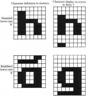
To get around this problem of the tall letters, we
could simply redefine them without the topmost dots. This however
would make them look odd - 'h' tends to look rather like 'n'. A
better way is to move the character set into RAM, displacing each
character definition upwards in memory by one byte (so that byte 1
goes into the byte 2 position, byte 2 into byte 3 etc.). This has
the effect of displaying each character one scan line lower on the
screen but still leaves us two scan lines for the descenders. This
means that the tall letters will not lose their tops. Listing 6
contains a BASIC subroutine to do this (lines 310-340) and then
redefines the descender letters as in Figure 1.
Listing 6
|
|
|
|
Line 270 resolves a slight problem. The lowercase
descender letters (plus comma and semicolon) have data in the last
byte of their character definition, which the above routine puts
into the first byte of the following character. Line 270 puts zero
into the appropriate character's first byte, thus avoiding the
display of unwanted data. The only other problem is that certain
characters (notably the ConTRoL graphics characters) have data in
the last byte of their definitions. Moving this data means that
these characters no longer display properly. I haven't bothered to
correct this, other than for the comma and semicolon but if you want
to use these characters, it is a simple matter to redefine them back
to their correct shapes. Having redefined the descender characters,
the program finally prints a silly message to show that it really
works.
That, then is Antic 3. You could of course design
other character sets, such as a Greek character set in this mode.
Virtually any type of text is sure to look better. Remember that
since the characters are still defined on an 8 x 8 grid basis, any
character set editor can still be used. I think there is great
potential in this mode, which has never been fully utilised.
PAGE FLIPPING
Page flipping is a technique whereby you can
change the picture on the screen instantaneously, without having to
clear it and redraw. It works by setting up two (or more) screens in
RAM, then flipping between them simply by changing the display
memory bytes in the DL. Listing 7 gives a very simple example of
this.
Listing 7
|
|
|
|
As you see, the process is very simple. Line 30
first clears some memory - 2K, enough for two Graphics 0 screens.
(The statement PRINT CHR$(125) can be used to clear any amount of
memory between the memory location found in registers 88 and 89 and
that in RAMTOP, location 106. For more information, see 'Mapping the
Atari', page 19.) Lines 80 to 100 write to the first screen by
directing screen and display memory pointers to it, and then alter
the pointers and repeat the process for the second screen. Line 160
is the core of the page flip routine. The display memory locations
in the DL are directed alternately to the two screens. By inserting
additional LMS commands into the DL, you could flip only part of the
screen while leaving the rest intact. Incidentally, you are not
restricted to flipping between screens of the same mode, but if
using different modes you must also change the DL. Try modifying the
above example to flip between Graphics 0 and 1.
There is an additional rather fascinating
possibility. What if we could flip very rapidly between the screens
- say in every vertical blank interval? This would take place so
rapidly that the two screens would appear superimposed. If the VBI
routine also changed character sets or colour registers, it might
allow you to construct Graphics 1 or 2 screens with 8 text colours,
to print upper and lower case characters on the same screen in these
modes, or to mix Graphics 0 text with a Graphics 8 display. To
demonstrate that this really does work, add Listing 8 to the above
example and re-run the program. Both screens will appear together,
using a simple VBI routine to flip the pages. The assembler source
code (Listing 9) is provided for anyone interested, and should be
easily modifiable for your own purposes.
Listing 8
|
|
|
|
Listing 9
|
10 *=$0600
20 ;equates
30 SYSVBV=$E45F
40 COUNT=$CB
50 DLLOW=$CC
60 DLHIGH=$CD
70 SDLSTL=$230
80 SETVBV=$E45C
90 ;set up for vbi
0100 PLA ;no. of args
0110 PLA ;discard hi-byte of 1st arg.
0120 PLA ;1st. page
0130 STA PAGE1
0140 PLA ;discard hi-byte of 2nd arg.
0150 PLA ;2nd. page
0160 STA PAGE2
0170 LDA #00
0180 STA COUNT ;set counter to zero
0190 LDA SDLSTL ;lo-byte of display list
0200 STA DLLOW
0210 LDA SDLSTL+1 ;hi-byte of display list
0220 STA DLHIGH
0230 LDA #6 ;immediate vbi
0240 LDX #VBROUT/256
0250 LDY
#VBROUT&255 |
0260 JSR SETVBV
0270 RTS
0280 VBROUT
0290 CLC
0300 LDA COUNT
0310 ADC #1 ;add 1 to counter
0320 STA COUNT
0330 AND #1
0340 BNE PAG1 ;show page 1 or 2?
0350 ;change page
0360 PAG2
0370 LDA PAGE2
0380 LDY #5
0390 STA (DLLOW),Y ;hi-byte of screen memory for page 2
0400 JMP EXIT ;back to O.S.
0410 PAG1
0420 LDA PAGE1
0430 LDY #5
0440 STA (DLLOW),Y ;hi-byte of screen memory for page 1
0450 EXIT
0460 JMP SYSVBV
0470 PAGE1 .BYTE 0 ;reserved space
0480 PAGE2 .BYTE 0 ;for hi-bytes of the two pages
0490 .END
|
Those of you not familiar with assembly language
can still use the routine - simply change the variables RAMTOP-8 and
RAMTOP-4 in the USR call to the highbyte of display memory for each
screen. You must ensure that the low-byte is the same for both
screens, as in the example.
Notice that some slight flickering does occur with
this example. This can be minimised by adjusting your TV set, and by
experimenting with the available colours. It appears best to use
dark backgrounds with high luminance foreground colours, but I will
leave you to investigate this further. See 'De Re Atari' p.2-10.
THE DISPLAY LIST INTERRUPT
The Display List Interrupt is a highly advanced
feature found on few other personal computers even today - not bad
for a machine first designed in 1979! The DLI really needs an
article all to itself, but hopefully this will provide enough of the
basic information to get you started. For an extensive discussion,
see 'De Re Atari', chapter five.
The idea behind the DLI is that when Antic finds a
DLI instruction in the DL, the 6502 main processor is forced to stop
what ever it is doing and carry out a short machine language routine
supplied by the user. Unfortunately, due to timing considerations,
there is no way of knowing exactly when on a given mode line the
desired effect would actually take place. For example, a colour
change could occur partway along a mode line - and exactly where
this change occurred might vary each time the DLI was called. There
is a solution however. Storing any number into register 54282 (WSYNC;
D40A hex) forces the microprocessor to wait until the horizontal
blank period before carrying out the required changes. Any changes
will therefore appear on the line below that carrying the DLI
instruction.
What sort of things can you do? Your routine must
be short, and therefore changes are limited, but you can change
colour registers, alter other graphics registers such as the
character base register, create sound effects and manipulate
player-missile graphics. Some examples are given below.
Listing 10
|
|
|
|
Listing 11
|
|
|
|
Listing 12
|
|
|
|
There are a number of steps to follow when setting
up a DLI. These are as follows:
1) Write your DLI routine. It must be short. The
time available varies between graphics modes, but ranges from 14 to
61 machine cycles. For detailed timing considerations, see De Re
Atari. Whatever else it does, your routine should first save all the
6502 registers you intend to use to the stack (necessary because,
unlike the vertical blank interrupt, the O.S. doesn't use DLIs and
so does not automatically save and restore the registers). It should
then address WSYNC as indicated above. Note that any registers
changed by the routine - colour, sound, etc. - should be the
hardware registers and not the more commonly used O.S. shadow
registers, otherwise the effect will not be properly carried out. At
the end of the routine, all 6502 registers used should be restored
from the stack and the routine should end with the Return from
Interrupt (RTI) instruction.
2) Place the routine into a protected memory area
such as page six.
3) Put the starting address of your DLI routine,
in low- and high-byte format, into the DLI vector location at 512,
513 (200,201 hex; VDSLST). Note that there is only one vector, and
if you intend to use multiple DLIs then each DLI should modify the
vector to point to the next routine. 4) Modify the DL to call the
DLI. To do this, add 128 (i.e. set bit seven) to the mode line
instruction of the line before the line on which you wish the change
to appear (see the discussion above for the reason for this). Note
that this means that you cannot use a DLI to alter the first mode
line of any screen.
5) Finally, enable DLIs by POKEing location 54286
(NMIEN; D40E hex) with 192. DLIs are disabled on powerup and System
Reset.
Listings 10 to 12 are three examples of DLIs. The
assember source code is also given (Listings 13 to 15) and should be
fairly self-explanatory. The first example is probably the simplest
possible DLI, it changes the lower part of the screen to yellow. The
top part remains blue because during the vertical blank period the
O.S. reads the RAM shadow register (not changed by the DLI - hence
the reason for addressing the hardware registers) and puts the
contents back into the hardware register. When you have this
running, try pressing a few keys. You will see that occasionally a
keypress is accompanied by a 'glitch' on the screen. This occurs
because the O.S. keyclick routine also addresses WSYNC and in doing
so interferes with the timing of the DLI. There isn't much you can
do about this, except not to allow input from the keyboard in your
program! I understand that XL owners can disable the keyclick with a
POKE 731,255 (do a POKE 731,0 to turn it on again). You might like
to try this and see if if works. (400/ 800 owners like myself
needn't bother, 731 is a merely a spare byte in our machines.) I
have tried the NOCLICK routine from Page 6 library disk no. 20 and
this does appear to prevent the problem.
The second example is one of sound generation
using a DLI. The advantages of this method are that your main
program continues to run independently of the sound effect.
Certainly, you could do the same thing using a VBI routine, but you
can turn off a DLI sound effect by removing the DLI instruction
from the DL, or more simply by disabling DLIs (POKE NMIEN with 64).
Do this with a VBI and you turn off the O.S. vertical blank routine
as well! The demonstration addresses the sound registers directly;
for more information on this, see 'Mapping the Atari' pp. 121-125.
The loop in line 140 is necessary because coming to the end of a
BASIC program - or the keyword END - turns off the sound. However,
pressing Break or the keyword STOP do not (try it and see).
The last example demonstrates the possibilities of
using a DLI to enhance player-missile graphics. Believe it or not,
the effect that is shown is achieved by using just one player and
one DLI. The way it works is that the player image data is first
read into six different areas in the player-0 memory map
(corresponding to six vertical positions on the screen) and the DLI
code set on six DL mode lines. The DLI is table driven and each time
it is called changes the colour, size, horizontal position and
priority registers. A simple VBI routine is used to move the player
horizontally (source code in Listing 16). In this third example,
there is an inbuilt delay (line 210) to show you the effect before
the DLI is enabled. Because the DLI is table driven, you can
experiment with it and see what effects are produced. The four
tables are in lines 310-380 and can all be altered. The position
table is not one of absolute positions, but of offsets from the
horizontal position stored temporarily in location 204, and then put
into the player-0 position register at 53248.
Next issue, in the concluding part of this
series, Steve Pedler looks at some advanced uses of the Display List
including scrolling.
Listing 13
10 *=$0600
20 ;equates
30 WSYNC=$D40A ;sync register
40 COLPF2=$D018 ;background colour
50 ;dli service routine
60 PHA ;save accumulator |
70 LDA #$FC ;new colour (yellow)
80 STA WSYNC ;wait for horizontal sync
90 STA COLPF2 ;do the new colour
0100 PLA ;restore accumulator
0110 RTI ;return control to processor
0120 .END |
Listing 14
|
10 *=$0600
20 ;equates
30 WSYNC=$D40A
40 AUDF1=$D200 ;audio frequency #1
50 COUNTER=$CB ;temporary counter
60 ;dli service routine
70 PHA ;save accumulator
80 LDA COUNTER ;get frequency |
90 STA WSYNC ;wait for horizontal sync
0100 STA AUDF1 ;change frequency
0110 INC COUNTER ;increase the frequency counter
0120 PLA ;restore accumulator
0130 RTI ;return control to processor
0140 .END |
Listing 15
|
10 *=$0600
20 ;equates
30 HPOSP0=$D000 ;horiz. position register, player zero
40 OFFSET=$CB ;offset counter into tables
50 SIZEP0=$D008 ;size of player zero
60 COLP0=$D012 ;colour of player zero
70 WSYNC=$D40A
80 PRIOR=$D01B ;priority register
90 POSTEMP=$CC ;temporary position counter
0100 PHA ;save accumulator
0110 TXA ;save x-register
0120 PHA
0130 PHP ;save status register
0140 LDX OFFSET ;get the offset into the tables
0150 LDA POSTEMP ;temporary position counter
0160 CLC ;clear carry
0170 ADC POSTAB,X ;add the position value |
0180 STA WSYNC ;wait for horizontal sync
0190 STA HPOSP0 ;do the new position
0200 LDA COLTAB,X ;get the new colour
0210 STA COLP0 ;and carry it out
0220 LDA SIZTAB,X ;get the new size
0230 STA SIZEP0 ;and carry it out
0240 LDA PRIORTAB,X ;get the new priority
0250 STA PRIOR ;and do it
0260 INC OFFSET ;increase the offset
0270 PLP ;restore processor status
0280 PLA
0290 TAX ;restore x-register
0300 PLA ;restore accumulator
0310 RTI ;return control to processor
0320 ;value tables follow
0330 POSTAB .BYTE 30,50,150,175,75,10
0340 COLTAB .BYTE 14,170,204,74,136,86
0350 SIZTAB .BYTE 1,0,1,3,0,1
0360 PRIORTAB .BYTE 1,8,1,4,8,1
0370 .END |
Listing 16
|
10 *=$0680
20 ;equates
30 HPOSP0=$D000
40 SETVBV=$E45C
50 XITVBV=$E462 ;vbi exit vector
60 POSTEMP=$CC ;temporary position counter
70 TIMER=$14 ;internal realtime clock
80 OFFSET=$CB ;offset into tables
90 SIZEP0=$D008
0100 ;initialize vbi
0110 PLA ;number of arguments
0120 LDA #7 ;deferred vbi
0130 LDY #VBROUT&255 ;lo-byte
0140 LDX #VBROUT/256 ;hi-byte
0150 JSR SETVBV ;enable vbi
0160 RTS ;back to BASIC
0170 VBROUT ;start of vbi routine |
0180 LDA #0
0190 STA OFFSET ;reset offset counter
0200 STA SIZEP0 ;and size register
0210 ;colour and priority are reset by system vb routine from shadow register
0220 LDA TIMER
0230 AND #1 ;slow things down a bit
0240 ;move by one colour clock every other jiffy
0250 BNE EXIT
0260 INC POSTEMP ;increase the temporary position counter
0270 LDA POSTEMP
0280 STA HPOSP0 ;and store it in position register
0290 EXIT
0300 JMP XITVBV
0310 .END |
top