It's annoying, to say the least, after having spent
£750 on a computer that has now been discontinued/discounted, to find you
are asked to pay an extra £25 for a set of O.S. ROM chips and then, if
your colour picture isn't central to your monitor screen, being asked for
another £20 for an updated Glue chip (and have you ever tried fitting a
Glue chip? .... forget it!).
The programs accompanying this short article are short
ST Basic or machine code utilities that will help you to overcome the
dreaded Glue chip problems via a software fix. This fix will work for most
colour software, and works by resetting the vertical synchronisation
signal to your monitor.
The U.K. version of T.O.S. in ROM format sets up the
video chip to generate 50Hz vertical sync pulses, and this has the effect
of shifting the screen over to the right of most currently available
monitors, unless you have Glue chip number C025915-38. This only happens
in low and medium resolution modes, since the sync is set to 70Hz for the
monochrome Atari monitor when in high resolution mode.
The problem of the screen shift can usually be overcome
by resetting the vertical sync to 60Hz once you have booted up and got the
ST into the screen mode relevant to the software that you wish to run.
The synchronisation is controlled by a register located
at $FFFF820A (within the video controller I.C.). The register is 8 bits
wide, but only the two least significant bits are used:
| BIT 0 |
If this bit is set then the sync pulses
are taken from an external source, if the bit is clear (normal
state) then the video controller provides the sync pulses. |
| BIT 1 |
If set, the controller produces a 50Hz
vertical sync, if clear, then it's a 60Hz sync. |
All that is needed is to clear bit 1 of the register to
get our 60Hz back!
The usual method of clearing bits of a register is to get the current
value of the register and perform an AND operation to ensure clearing the
desired bits but leaving others unchanged. To clear Bit 1, and leave all
the others, we must AND the current contents of the register with $FD:
$FD =
11111101 binary
^
clear Bit 1
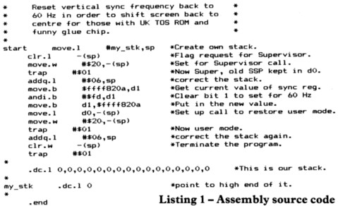
The assembly language programmer will need to get into
supervisor mode to change the register since it is within the protected
memory area. The code is shown in listing 1.
If the machine code is assembled, a stand-alone program
is created which can even be put into an 'Auto' folder on any of your
disks containing low resolution colour software - thereby enabling you to
automatically recentralise the screen on switch on. DON'T put the 'Fix'
program on a protected disc - it may corrupt the program - and don't
expect the 'Fix' to work with Brattacas, or any other software that has to
be booted from disk at switch on.
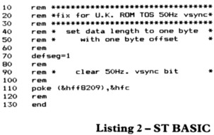
For the Basic language programmer, it is far simpler to
directly poke the whole byte to the relevant address, and listing 2 does
this. Obviously only two lines of the program are significant, since all
'Rems' and the 'end' statement can be omitted. Type in the program, save
it to disk first, then try running it in low or medium resolution mode,
and finally run your colour program.
A BONUS
Even if your Glue chip is OK, you'll still find the
programs listed here useful. When the ST is set to U.S. 60Hz sync, the
screen area enlarges considerably, and picture quality improves,
noticeably reducing the amount of often seen shimmering and 50Hz pulsing.
Try it and see!
top