Find out how to control the graphics on your ST. Colm Cox brings
you some of the secrets of programming the ST with examples in ST
BASIC, C and Assembler
This issue we will take a first look at graphics on the ST. This
machine is a complex beast in the field of graphics, just look at
the specification — 640 x 400 in mono (2 colours), 640 x 200 with 4
colours and 320 x 200 with 16 colours. There is also an enormous
palette of 512 colours to choose from and 32K of video ram! I will
split my description of graphics on the ST into two parts thus,
hopefully, giving the features the ST boasts a good airing.
THE CUSTOM GRAPHICS CHIP
To start we need to take a look at the hardware registers of the
custom graphic chip — 'The Shifter' — used by the ST but first we
must discuss the concept of logical and physical screen bases.
The ST takes an area of 32K of ram and then converts it into a form
suitable for display. The area of ram being displayed is called the
'Physical screen base' however when we give a command, for instance,
to draw a line between co-ordinates 10,10 to 100,50 the ST must
change screen memory for us to see the line. The area of memory that
the ST alters is called the 'Logical screen base'. This can be the
same as the Physical screen base but the Logical and Physical screen
bases can be different, allowing us to have a picture displayed on
the screen while another is drawn. When the second picture is drawn,
it can be displayed instantly which opens the door to an animation
technique called 'Page flipping' where a series of slightly
differing pictures are drawn, held in memory and then rapidly shown
one after the other giving the illusion of movement.
THE REGISTERS
The video chip's hardware registers start at address $FF8200 and
continue on to $FF8260
$FF8201 - (8 bit R/W) High byte of physical screen base
address.
$FF8203 - (8 bit R/W) Mid byte of physical
screen base address.
The low byte of the physical screen base address cannot be changed,
it always is zero, which means that the ST can only display areas of
ram with starting addresses which are multiples of 256.
The next three registers are quite interesting — they provide the
address of the word presently being displayed. They are read only
and, as they increment at such a fast rate, are excellent random
number generators.
$FF8205 - (8 bit R only) High byte of address of word
currently being displayed.
$FF8207 - (8 bit R only) Mid byte of address of word
currently being displayed.
$FF8209 - (8 bit R only) Low byte of address of word
currently being displayed.
$FF820A - (8 bit R/W) This byte controls the synchronisation
of the monitor and display chip.
Bit 1 controls the screen frequency - 0 = 60hz, 1 = 50hz (See Dave
Keel's article in Page 6, Issue 23, entitled 'A Bigger Screen'). The
effect of bit 1 is to enlarge the screen area on mid/low res
monitors. This bit has no use with mono monitors. Bit 0 allows the
syncronisation of the monitor to be either internal or external.
Internal = 0 (normal setting) means that the video chip takes care
of picture sync. External = 1 means that the sync pulses come from
an outside source, e.g, a video camera etc. The practical effect of
selecting external sync is that you get no picture! Try (from
STBasic): DEF SEG= &HFF8200: POKE &HA,&HFD. To get your picture back
(you'll have to type 'blind') type POKE &HA,&HFC.
$FF8240 - (16 bit R/W) Colour palette register
0
$FF8242 - (16 bit R/W) Colour palette register 1
$FF8244 - (16 bit R/W) Colour palette register 2
..............
$FF825A - (16 bit R/W) Colour palette register 13
$FF825C - (16 bit R/W) Colour palette register 14
$FF825E - (16 bit R/W) Colour palette register 15
Each of the colour registers take a 16 bit value
which specifies the intensity of the red, green and blue parts for
that colour. The form of the 16 bit word is $XRGB where the Hex
digit X has no function and the digits R,G and B detail the
intensity (0 to 7) of that particular colour. This is where we get
the specification 512 colours (8 x 8 x 8).
The user with a mono monitor can try: DEF SEG= 0:POKE &HFF8240,1
For users with colour monitors, a very powerful
technique called colour rotation is available — see Steve Pedler's
article in issue 28 for an explanation.
Certain values relating to the screen are stored in low memory by
the operating system. This is similar to the idea of shadow
registers on the 8 bit Atari machines where values are stored in low
memory and then transferred to the hardware registers every 60th of
a second. A similar situation is the case on the ST.
$44C - (16 bit R/W) Graphic resolution.
This register allows the user to switch between resolutions. It
works only when switching between low and medium resolution, as
switching from high to low or low to high is impossible because
different monitors are required. This register also allows the
programmer to determine what the current screen resolution is. The
values stored in this `register' are: $0 = Low res, $100 = Med res,
$200 = High res.
$44E - (32 bit R only) Logical Screen Base address.
This 4 bit register contains the logical screen base address. I have
used this in Listing 1 (STBasic). The program demonstrates the
technique of page flipping. I have used only two screens but you can
use as many as you wish, providing you can find sufficient memory!
DESIGNING THE SOFTWARE
That's the hardware registers but, as with most computers, the most
important area is the software interface between the hardware and
the user.
The ST has more than its fair share of software supporting the
impressive specifications outlined at the start of this article. I
aim to start at the lowest level and work up to the heights of GEM,
but we must first discover how the ST stores the data it uses to
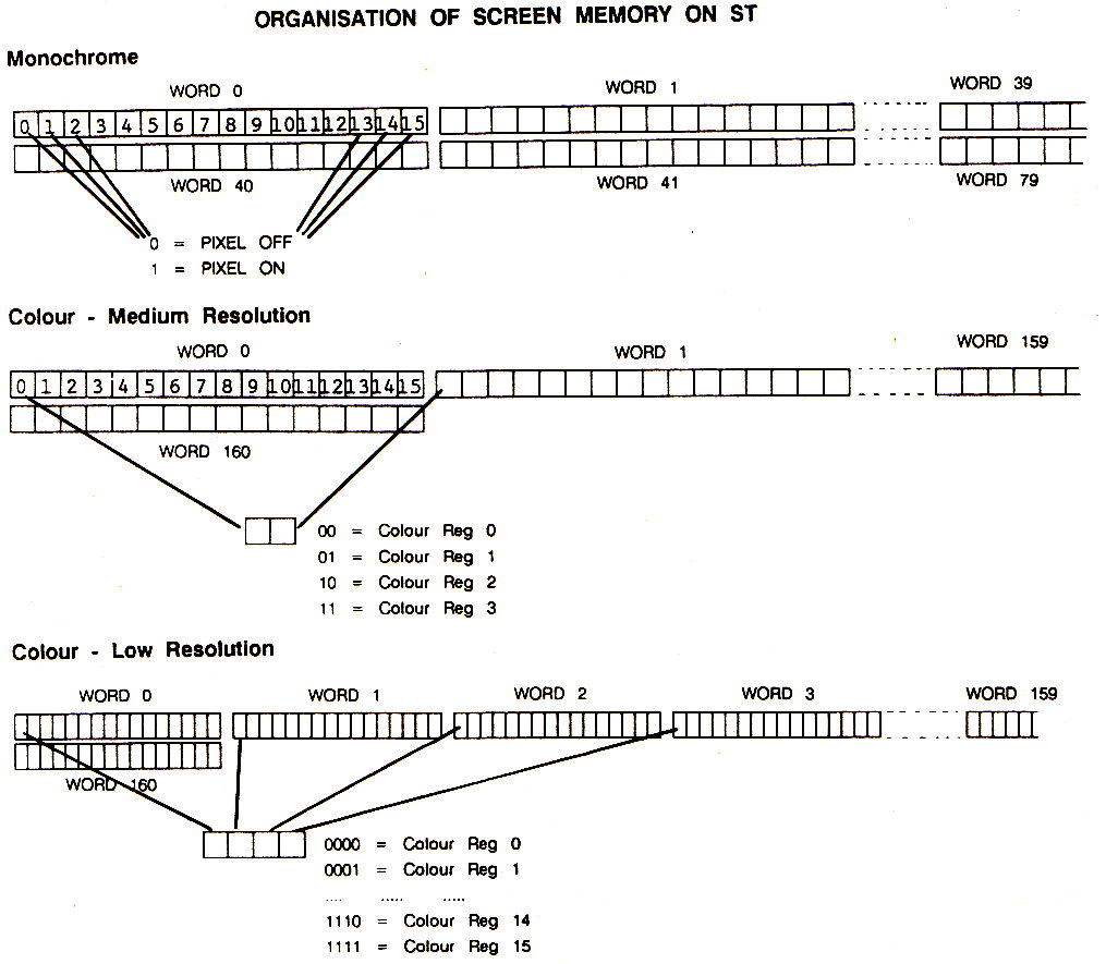
represent what we see on the screen. In monochrome mode, each bit of
each word represents the state of a pixel. A bit at 0 means that
pixel is off, a bit at 1 means the pixel is on — see Figure 1.
In medium resolution, things become more complicated, the ST uses
the screen memory in a different way to the norm. See Figure 2 for a
pictorial explanation. Two contiguous words are `joined together' —
bit 0 of word 0 and bit 0 of word 1 combine to give a two bit value
which is then mapped onto the appropriate colour register. In low
resolution, the same applies but in this case 4 contiguous words are
used — see Figure 3.
Now you know how the ST stores its screen data, but where does it
store it? As I stated above, the screen can be moved in memory,
however on power up the ST determines the amount of memory available
and then takes 32767 from the address of the last usable byte. In a
512K system the last usable memory address is $7FFFF. $7FFFF — 32767
= $78000 therefore the 520ST places its screen at location $78000.
So, you can now access the screen directly with POKE commands. But
wait! Didn't you buy the 16 bit ST because it was one of the most
powerful computers available? And here you are using a POKE command
to access graphics — there must be an easier way!
USING LINE A
The Line A interpreter is a feature common to all 68000 systems.
When the 68000 encounters an instruction beginning with $A, such as
$A000 it generates an 'exception' (I hope to discuss exceptions in a
future article). The ST jumps to a section of code which interprets
the meaning of that op-code. The Line A commands can be made to do
whatever you wish and, on the ST, they are the ground level graphic
interface.
There are 14 Line A commands, all of which take the form of: $AOOX
however for the 'C' and ST Basic programmer most of these commands
duplicate some of the functions
provided by the VDI interface. To save space, I will examine only
those that add worthwhile extensions to the ST. Of the 14 Line A
commands, only three are significantly different. These three
commands are 'Initialise Line A', 'Draw Sprite' and 'Erase Sprite'.
As the Line A interface is essentially an aid to assembly language
programmers, access from 'C' or ST Basic is not easy but I have
included the necessary code to allow you to use these functions from
your 'C' or ST Basic programs.
I will now discuss the three commands — but first, I must explain a
Hot Spot! The Hot Spot is a point of reference on a sprite
determined by the programmer. When the Draw Sprite command is given,
the x and y co-ordinates refer to this point on the sprite. Let's
take an example. Suppose the hot spot is defined by the programmer
to be in the centre of a sprite. All subsequent Draw Sprite (x,y)
commands will draw the sprite with the co-ordinates x,y at the
sprite's centre.
THE LISTINGS
Listing 1 shows how to use multiple screens from ST Basic, Listing 2
contains a basic loader which allows the user to access Line A
Sprite functions from ST Basic and also shows how this utility may
be used. Listing 6 is 'C' source code which shows how to use Line A
from 'C'. Listing 3 is the required binding for HABA C. Listing 4 is
the binding for 'normal' C's — see my article last issue describing
the need for the two listings. Finally, Listing 5 is an assembly
language demonstration of how to access Line A sprites.
That's about it for this issue — next time I'll be taking a look at
more features of ST graphics such as raster forms. Good luck with
Line A which is a very powerful feature allowing quick and easy
access to the powerful graphic features provided by the ST.
As I mentioned in the last issue, if you are having any trouble in
using any of the code I have included with my articles, I can be
contacted at CoIm Cox, 10 Graigue Court, Poppintree, Ballymun,
Dublin 11, Eire but please, please, please include a S.A.E!
 Listing 1
Listing 2
Listing 3
Listing 4
Listing 5
Listing 6
________________________________
DESCRIPTION OF LINE A COMMANDS
INITIALISE LINE A
Line A
opcode: $A000
Input: None
Description: This opcode must be executed before any other
Line A opcodes are given. The function of this opcode is to
initialise the areas of memory used by the Line A system. If you
don't execute this opcode, none of the other opcodes function
correctly — you have been warned!
DRAW SPRITE
Line A
opcode: $AOOD
Input: Address of a Sprite Definition Block in AO
Address of a buffer in A2
X-Position of sprite in DO
Y-Position of sprite in D1 (AO,A2,DO,D1 are 68000 registers)
Description: This command draws a 16 x 16
pixel sprite at the screen location contained in DO and Dl. The
actual definition of the sprite is held in a `Sprite Definition
Block', who's layout I have described below. The size of the block
is always 74 bytes long. The buffer's size is dependant on the
resolution you are working in. It's function is to retain the image
under the sprite, so that when the Erase Sprite function is called,
the background can be restored, thus erasing the sprite.
ERASE SPRITE
Line A
opcode: $A00C
Input: Address of buffer in A2
Description: This command restores the area
under a sprite drawn with the Draw Sprite command.
BUFFER SIZES FOR DIFFERENT RESOLUTIONS:
High res 74 bytes, Medium res 138 bytes, Low res 266 bytes
SPRITE DEFINITION BLOCK
Word 0: X-Offset to Hot Spot (from top left corner)
Word 1: Y-Offset to Hot Spot (from top left corner)
Word 2: 0
Word 3: Background colour
Word 4: Foreground colour
Words 5 to 36 hold the actual definition of the sprite are
held, along with a mask. The mask is an area slightly larger than
the sprite within which the sprite exists. If you wish to see this
effect at work, move the mouse pointer over a black area of the
screen. What you are seeing is the white mask with a black arrow
inside it.
Word 5: Mask line 0
Word 6: Definition line 0
Word 7: Mask line 1
Word 8: Definition line 1
......
Word 35: Mask line 15
Word 36: Definition line 15
top