In this first article of a new
series Mark Fowlis takes a general look at the various ways you can
expand your Atari 400/800, XL or XE
If you are at all interested in the hardware side of
computing you will, no doubt have looked through the multitude of
computer interfaces, expansion modules and gadgets available at
local computer stores. If I were to ask you which computer is the
best for adding on these bits and pieces, which would you say? The
BBC? Spectrum? Commodore?
Wrong on all counts! The Atari beats them all hands
down with its Parallel Bus Interface (the rear port connector to us
mere mortals), a cartridge port which can also be used or expansion,
two (or in some cases four) joystick ports, which can be
reprogrammed as outputs or inputs, and a serial port.
Why then, if the Atari is so great for expansions,
are there such a a small number of Atari add-ons and why are those
that are available so expensive? Well, there are several reasons
behind this. Many of the other computers lack the features already
in the Atari and need these extra add-ons to even compete, but a
more significant reason is that Atari Inc. has always taken years to
release any hardware details to the public and, as a result, there
are hardly any expansions made for the Atari. The manufacturers can
charge higher prices as there is little competition.
DO IT YOURSELF
For those owners who want to add something to their
Atari, help is now at hand in the shape of this series of articles,
which will teach you how to build your own add-ons at a fraction of
the cost of ready-made units in the shops. This first article will
take an overall look at the various expansion possibilities and
later articles will go on to discuss specific projects.
If you are seriously considering expanding your Atari
you will need several essential tools. These are a low power
soldering iron suitable for electronics, some solder, wirecutters
and metal tweezers or snipe-nose pliers. A multimeter and/or a logic
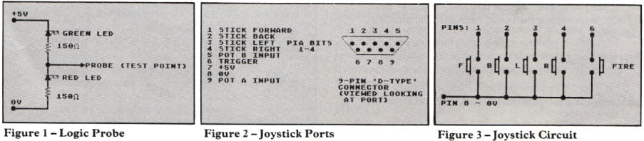
probe is also invaluable. For those of you who don't have a logic
probe an extremely simple circuit is provided in Figure 1. This will
when connected tell you if the point probe is touching at logic
level 1 (i.e. + 5V), or logic 0 (i.e. OV). These are the two basic
voltages within the circuitry of most computers, except for power
supplies and video circuits which do not concern us anyway. Hence
for interfacing we will be using TTL (transistor-transistor logic)
chips as these handle the correct levels.
Let's now take a look at each of the ports available
to us.
THE JOYSTICK PORTS
These are the most widely known expansion ports on
the Atari. The connections of these ports are shown in Figure 2.
Pins 1-4 and 6 are normally at +5V level, and these are connected by
a switch to Ov when the joystick is pushed in a direction — see
Figure 3. With five push-to-make switches you can easily make an
arcade-type joystick.
The PIA (or joystick) bits provide the input to one
(or two in 400 800 models) 6520 PIA chip(s) read by the computer.
The PIA (Peripheral Interface Adapter) can re-configure these lines
to be either input (as normal) or output depending on the `direction
control register' in the chip. We can control this quite simply.
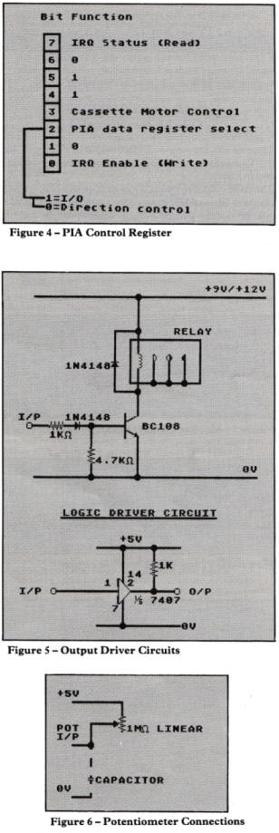
Figure 4 shows the bit use of the control register(s).
The important bits are 2 and 3. Bit 3 you have
probably come across before in POKE 54018 with 52 or 60 to switch
the cassette motor on and off. Bit 2 controls the use of the data
register. If bit 2 is high (set to 1) then any data written to the
data register goes to the output and data on the inputs can be read
from the data register. If bit 2 is low (set to 0) then the data
register gives access to the port direction control register. For
each bit (which represents an input/output line), the level
determines the direction. If we put a 0 in bit 5 then line 5 will
be an output.
Conversely putting a 1 in a bit makes it an input.
Bit 2 is then set back to 1 so that data can be read and written to
the data register. Lucky 400/800 owners have two sets of these and
can have 16 controllable lines. In the 600/800XL and 130XE the
second PIA is used for memory control and management.
If we wish to use the port as an output we will need
so kind of driver circuit as the outputs can only handle a small
load. Figure 5 shows some typical driver circuits for various loads.
The limitation of the joystick ports is that they
only have 10 lines for digital data, if we include the two trigger
lines which are always inputs. We can therefore only have expansions
using a limited number of connections. We could drive the lines to
act as a serial interface for us, but this is a lot of work, mostly
in writing the software, although it can be very effective.
Some sort of program must, however, be loaded in to
operate any joystick port driven interface and as this program
resides somewhere in memory, may be written over or ignored by other
programs. As a result, you cannot guarantee that your interface will
work with all commercial software (despite the claims of certain
manufacturers!), and obviously you cannot use joysticks as well!
The joystick ports are also designed to accept
light-pen input. These connect into port 2 (or 4 on the 400/800).
Unlike other computers, the light pen circuitry can be really simple
as all we need is a light sensitive switch to connect the trigger
line to OV when the electron beam of the television screen passes
it. As the beam scans the screen rapidly we need a fairly fast
device. Many designs have been produced before so I shall refrain
from yet another light pen circuit unless there is a demand for one.
The light pen X and Y screen positions are provided by the Atari in
memory locations 564 and 565.
The potentiometer inputs A and B are normally used
for the paddle controllers if you have any, however they can be used
to read the position of other variable resistors (potentiometers),
see Figure 6. This could be useful in many applications such as
position sensing in robots, graphic input devices, paddles, etc.
The values are read from the following locations:
Port 1 — POT. A — 53760 ($D200)
— POT. B — 53761
Port 2 — POT. A — 53762
— POT. B — 53763 ($D203)
The 400/800 computers have yet another four inputs
(53764-53767).
We can use smaller value potentiometers if we connect
a capacitor from the potentiometer input line to OV. This slows down
the charging of the internal conversion capacitor, making the
computer think the resistance of the external potentiometer is
larger. This is a case of trial and error for individual
potentiometers and is only useful if you MUST use one with a smaller
value.
If the
reading of the pot inputs is being done in machine code we may
require some other locations:
ALLPOT — 53768 ($D208) gives the status of the
converters, 1 bit representing 1 converter. A bit set to 1 means
that the value of that input is valid.
POTGO — 53771 ($D20B) starts the conversion process on the inputs.
Also of interest is bit 2 of location 53775 ($D2OF)
which when set to 1 enables fast scanning of the inputs. This
fastscanning is in 2 TV scan lines (128uS) but is not as accurate as
the normal scan.
A final note on the joystick ports — the +5V supply
is not intended for heavy loads or lots of circuitry. Anything more
than a few logic gates should have its own power supply.
MONITOR OUTPUT (XL/XE models only)
This provides the composite video output to a
monitor. Note that TTL monitors will NOT work! The pin connections
are shown in Figure 7.
The audio output is around 0.75V peak-peak which is a
little too high for Hi-Fi 'AUX' inputs which want around 150mV pk-pk.
We can step down the voltage using a potential divider — see Figure
8. Now you should be able to have Hi-Fi sound from your Atari! Check
the input levels to your Hi-Fi first though, R1 may need to be
larger if the input level is less than 150mV.
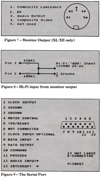
THE SERIAL PORT
This is pretty difficult to use unless you intend
using a computer at the other end to decode the signals and send the
appropriate reply codes. As you can daisy chain a number of devices,
each data message has a device address encoded and the destination
must acknowledge each frame from the computer. Personally I would
not advise expanding via the serial port as it is too complex and
not particularly fast. Also any driving software must handle the
device by the standard SIO calls. For the interested, the pin
connections are in Figure 9 and a good description of the operation
can be found in the 400/800 reference manual available from Atari.
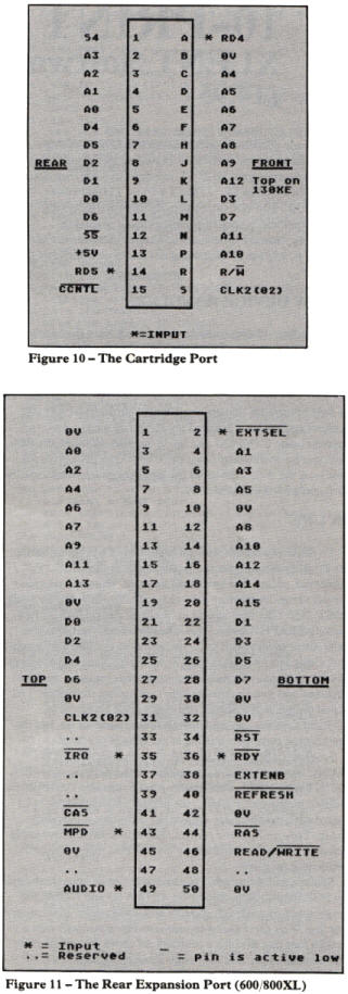
THE CARTRIDGE PORT
Although predominantly used for ROM cartridges, the
cartridge port is an extremely useful expansion port giving us a 16K
block of memory for registers and I/O. The pin assignment is shown
in Figure 10 and includes:
* Address lines AO to Al2 (8K coverage)
* Data Bus (DO to D7)
* R/W — Read/Write
* S4 — Right slot ROM select line. ($8000 — $9FFF).
* S5 — Left slot ROM select line. ($A000 — $BFFF). * RD4 — Right ROM
present. ( + 5V if it is)
* RD5 — Left ROM present. ( + 5V if it is)
* 02 — System clock.
* CCTNL' — ROM Bank Control select line: driven by any R/W to $D5000
to $D5FF. Used to select 1 of 2 ROMS in the area selected. (Supercartridges).
We can fit 32K of ROM into a cartridge and select
between two banks of 16K in the available space ($8000 to $BFFF).
The only difference with using the cartridge port is that you must
use cassette or disk based languages as the cartridge expansion will
occupy the cartridge area, hence the Assembler/Editor cartridge
cannot be used! We can however write our programs before and convert
them to Basic DATA statements for loading by the inbuilt Basic.
To connect to this port you will need a 15 way double
sided edge card of 0.1 inch spacing contacts to plug into the slot.
This could then be connected to a card frame for further expansion.
Alternatively for a chosen application with a small number of
components a 'cartridge' could be made on a double-sided p.c.b.
To interface to the cartridge port we must, in most
cases, make use of the right hand slot (i.e. $8000 to $9FFF) as the
left hand slot ($A000 to $BFFF) is occupied by Basic. If we are
using a purpose written machine code boot program, however, we could
use either or both halves.
THE PARALLEL BUS INTERFACE (XL/XE only)
One of the greatest mysteries of the newest range of
Atari computers is the rear expansion port. Hardly anyone seems to
know how to use it, and there have been a small number of slightly
confusing articles. Adverts too, manage to confuse the use of the
port. We shall now set history straight (I hope!).
The port presents us with the full address bus of the
computer AO to A15, allowing observation of any memory location —
see Figure 11. The data bus is also present. Read/Write and the
system clock are provided too. Where this port really starts to
differ is in the extra useful lines ....
CAS - Column Address Strobe, output for RAM
addressing.
RAS - Row Address Strobe, output for the same.
AUDIO - Audio input allowing you to have sound feeding
through your T.V./monitor speaker.
RESET - Output, to reset any expansions on power-up etc.
REFRESH - Refresh timing output.
MPD - Math Pack Disable Input. Disables Floating point ROM
($D800 to $DFFF) for parallel bus interfaces.
IRQ - Interrupt request input.
READY - Ready input. Used for slow memory devices.
EXTENB - External decoder output for PBI
devices. If you want to use the expansion for callable devices such
as disk drives then you need this.
EXTSEL - Input to disable internal RAM, to allow input. This
is VERY useful ...
Note that there is NO way of disabling the operating
system from the port. Some recent expansion units claim to be
expandable to allow multiple Operating Systems via the rear port,
however these will need internal modification of the host computer
thus invalidating your guarantee.
There are two ways of using the parallel bus
interface. Firstly, as Atari intended, it may be used as a device.
This could then be handled by the standard calls such as LIST "P:"
etc. However this requires a 2K device handler ROM to overlay the
floating point ROM. It might just be a little over the top if we
want a simple I 0 port and don't really want to spend time
programming 2K ROM's and writing device handlers! Secondly, you can
use it, as it probably will be used in nearly all cases, as a
powerful expansion port.
130XE owners may well be getting worried by now.
Where is the massive expansion port I am talking about? Apparently
Atari were not too happy that very few products had been released to
use the rear port on the 600/800XL, so they simplified it to a
'cartridge port expander'. Not one of the cleverest moves for, as in
the cartridge port, you cannot use a cartridge and a rear port
expansion! So for 130XE owners, the same rules apply as for the
cartridge port.
COMING NEXT
That's the overview of the expansion possibilities. I hope that it
has whetted your appetite. Next issue I'll be revealing the details
of the 130XE cartridge port expander (the equivalent of the rear
expansion port) as well as the 400/800 rear expansion bus (Atari's
biggest secret!). Also I'll be showing how to use the rear expansion
port to connect to a multitude of projects.
_________________
WARNING: Unless you are absolutely sure you
know what you are doing it is possible to damage your computer when
attaching any expansion circuits. Neither the author nor PAGE 6 can
accept any responsibility for any damage resulting from any project
undertaken as the result of suggestions made in this series.
top