A Bird's Nest
Falcon recasing
by Lyndon Amsdon
When the
Falcon was released it looked pretty much
like an ST from 1985, surely this was not
a good strategy by Atari, or did it think
this would make it instantly recognisable?
Who knows, but what I do know is that the
old case is far too limiting for such a
powerful machine. The Falcon was sold with
very slow 2.5" drives and very little
space for expansion, this was all powered
off a PSU that was crammed into the case
which causes quite a lot of heat to build
up.
These are
just some of the better reasons to put your
precious Falcon in a tower case with that
fast 3.5" IDE drive that had to be
pulled out of your PC because Windows XP
wouldn't fit on it. You'll get a lot better
cooling, which, combined with a better PSU
will help make the machine more stable.
The CT60 (a super 68060 booster) also requires
the ATX style power supply that is common
in all modern tower cases because it needs
3.3V which the Falcon PSU doesn't supply.
The main
thing you need for this project is patience
and preparation. Start off by stripping
the computer right down to the motherboard,
removing any internal drives and the PSU.
Next, get a piece of card the same size
as the motherboard and place the motherboard
on top of it. Draw around it with a pen
and mark out roughly the places for the
ports and any headers on the board (like
the IDE). Also familiarise yourself with
the board and check for loose wires on any
hardware upgrades while you're at it. Give
it a gentle dust down as well as the Atari
ST style cases tend to collect dust.
Take the
piece of card and pop into your local computer
shop to see it it'll fit in a PC full tower.
The tower case needs to be at least 50cm
high. You may get some funny looks so just
say your motherboard is larger than normal
because it's so good!
The ST and
Falcon motherboards are a lot longer than
PC ones so there is some metal work involved.
The majority of full tower cases are split
in two sections, one at the top for the
drives and the lower section for the motherboard
and cards. There is a metal strut separating
these two sections and a piece of this has
to be cut so the board can get in.
|
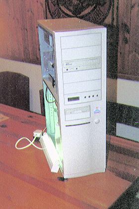
Tower case with
side off. Notice the two struts
that run from front to back,
seperating the two sections. |
When you
feel the case is fine then buy it and when
you get home remove everything off it including
PSU, drive carriers and if you can, the
front panel. Try fitting your card template
in and see what needs to be cut. Be extremely
careful when you do cut as the metal is
very sharp and in my second tower job I
covered the sharp edges with insulating
tape as I sliced the top of my knuckle off
on the STE tower, ouch.
Tools I used
were a junior hacksaw (with a sharp new
blade, it does help!) and a Dremel fitted
with a circular cutting wheel attachment.
My Dremel was too weak to actually cut the
tough steel so I used it to score and then
I used some pliers to bend it back and forth
until it snapped off. File the rough edges
smooth and make sure you clean out any metal
fragments, you don't want these anywhere
near your sensitive motherboard.
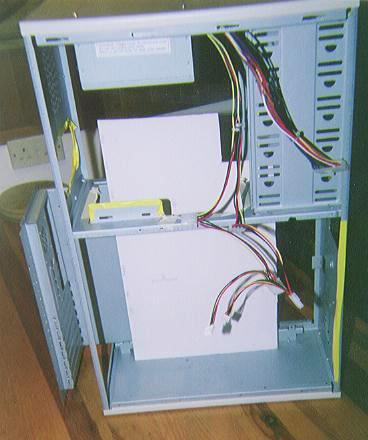
|
This shows the
piece of card in place. As you
can see the case was stripped
right back and sharp edges covered
with insulating tape. |
Now you'll
have to move the tower's PSU as the chances
are it will hit the motherboard when it
is in place. I mounted it at the top of
the case. The power supply had some screws
on the top to keep its enclosure together.
I removed these and bought some slightly
longer ones so I could drill holes in the
top of the tower case and screw through
holding the power supply up there.
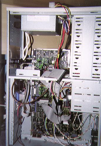
|
The PSU had to
be moved to make way for the
large Falcon board. |
When you're
happy try fitting the card template in place
and see if any adjustments are needed. When
it fits fine bring in the Falcon motherboard
and see if this fits. Leave the metal shielding
on the back of the motherboard but remove
the top shielding for easy access to the
components. Position the motherboard remembering
that you'll probably have to sacrifice a
couple of 5.25" drive bays. Remember
the connectors at the bottom (cartridge,
MIDI...) so leave space if you need to use
them. On my Falcon I didn't want to use
these so I managed to get the gap from the
bottom of the case to the bottom of the
motherboard down to only a few centimetres.
You can get right-angled plugs to fit the
MIDI ports from Maplin so you don't have
to leave a huge gap, but if you use the
cartridge port for dongles and other add-ons
then you may need up to 10cm. Take into
consideration where the back ports will
be lined up against the tower's back panel,
leave roughly 5cm here as well.
Now use marker
pen to stencil the motherboard's mounting
holes onto the tower case, where you'll
drill holes. Please remove the board before
you start drilling these! Use 6-10mm board
spacers then use some small bolts (about
12-15mm long) to hold the motherboard in
place, remembering to use fibre washers
on the motherboard side. Don't tighten them
all the way up as there is still a fair
way to go. You'll need to remove the board
again to work on the electronics.
You'll need
to make or find leads to attach the ports
to the back of the tower case. I recommend
Maplin and Farnell. Maplin even stock those
rather odd 13-pin and 14-pin DIN sockets!


You'll also
need to extend the floppy ribbon cable.
The motherboard doesn't have a header that
simply unplugs, so you have to undo the
latches either side of this and carefully
pull the ribbon cable out. Now use a PC
floppy cable and snip off the connector
that connects to the PC motherboard. Place
the end of the ribbon cable over the Falcon
motherboard's connector so the red stripe
is towards the back of the motherboard and
each wire is in its groove. Use the end
of a match stick (not the ignitable end)
to push down the individual wires one by
one. After you think the wires are down,
place the connector's top on and press quite
firmly. If it doesn't latch on then you'll
need to press the wires down a bit more
with the matchstick.
If you have
a Falcon you will probably want to use a
decent, fast 3.5" drive so you can
buy an adaptor. These are generic so a good
computer shop may have one, although they
are not that common. Wizztronics sell them
but you should be able to find other sources
of them. I believe they are also used on
Amigas.
If you are
attempting this on a normal Falcon without
a CT60 then you will need a new power switch.
You'll need to change the power switch from
the momentary type supplied to a latching
one. If you look through electronics catalogues
you'll probably find something very similar
to the one in your case but of a latching
type. Use the wires off the old switch and
solder them to the new switch. Keep the
old switch if you're intending on using
a CT60 as you'll need to fit that momentary
switch back in place.
All the front
panel switches and LEDs have small plugs
to fit headers mounted on the board. I used
a single row header to mate with these plugs
so they could be disconnected easily without
having to unsolder. At the moment the CT60
is still in development but it will come
with an ATX power supply connector so it'll
be a "plug-and-play" affair. The
CT60 will also support the PSU's full features
like automatic shutdown. However, with a
normal Falcon, work has to be done to accept
this newer PSU.
Find the
grey wire coming out of the PSU (may be
labelled as PS-ON on the PSU's enclosure)
and a black ground wire to connect to the
power switch header. Polarity isn't a concern.
This will now turn the PSU on. Check by
plugging in the PSU and connecting an old
hard drive or fan up to the power connector.
It'll be a good idea not to cut off the ATX connector
if you intend to use a CT60.
The power
LED is quite simple and requires taking
one of the 5V wires (red) and putting a
100 ohm resistor in series with the LED
and then taking this to ground. LEDs only
work one way around but it won't destroy
it having it around the wrong way so play
around before finalising the soldering.
|
This is how to
connect up the new PSU to the
Falcon connector. Please check
the voltages in case your PSU
doesn't follow the standard
for these power supplies. |
To use the
reset switch on the front of the tower case
you need to get the reset header and connect
the two reset wires across the capacitor
near the 3.6720MHz oscillator. It's a large
axial type. Polarity of the reset wires
is also not a concern.
|
These points on
the Falcon hook up to the tower's
reset switch. |
This is a
freeware schematic I used to construct my
multi-scan adaptor. When the Falcon is connected
to a multi-scan monitor that is capable
of a horizontal sync. down to 15KHz the
switch can be used to select VGA or RGB
mode. Warning: trying to run in RGB mode
on an old VGA monitor may cause permanent
damage to it if it is not designed to work
at 15KHz. This switch can be switched in
the middle of a session without having to
do a reset, which is particularly useful.
The change takes place when a program is
run that checks the type of monitor attached
like most demos and games do. Use shielded
wires to stop ghosting and any other forms
of noise and distortion on the screen.

|
A freeware adaptor
for selecting between RGB and
VGA for multi-scan displays.
[Click
to enlarge] |
SCSI is quite
difficult if you wish to have an internal
bus as well as external. I used an internal
style 50-pin Micro D, IDC connector to connect
to the Falcon's SCSI 2 port. This is crimp-on
which uses very fine ribbon cable with a
pitch of 0.025 inch, the same as SCSI 3.
You then need to solder on internal SCSI
cable. I used 50-way with 5 headers. This
went around the front for the drive bays
then back to the back panel where I soldered
it onto a SCSI Micro D port, just like the
one on the back of the Falcon. This was
simply a case of wiring pin 1:1, 2:2 and
so on up to 50:50. You may wish to use other
plugs inside your Falcon as newer drives
commonly come with SCSI 3 connector. Look
at Connect World (http://www.connectworld.com) for pin-outs for
all the SCSI connectors. Just match up the
names when wiring up. The pin numbers for
the connectors should be given on the connector
itself, you may need a magnifying glass
on those Micro D connectors! Avoid SCSI
differential drives (LVD: Low Voltage Differential)
altogether for the Falcon.
The keyboard
was the original keyboard but I extended
the lead and placed a mini DIN 8-way plug
on the back of the tower. I used a spare
ST case and carefully cut off the back to
make it smaller. The Falcon's keyboard was
put in there as it had Keyclicks which isn't
too bad a feel compared to the spongey ST.
I would recommend hooking up a Mega ST keyboard
though as these have a better feel and it
took a lot of time to cut up the case. There
are free schematics on how to do this, or
you can buy an adaptor for a PC keyboard
and mouse called Qwertyx from Mario Becroft.
|
My Falcon keyboard
sitting in half an ST case. |
The light
for the hard drive on the front of the tower
case can be connected straight up to the
keyboard connector. I recommend soldering
two wires to the underside of the board
where the connector pins come through. This
light will function just like the one found
on the keyboard.
|
Hooking up the
tower's hard disk activity LED
to the Falcon. |
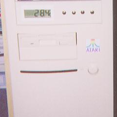
To finish
it off I replaced the stock LEDs in the
case with super-bright blue LEDs. I then
made a custom Atari Fuji logo badge to fit
the 25mm square on the front of the case.
I got a logo and resized it in Imagecopy
then printed it out and laminated it for
durability. I also built a special temperature
display that controls the fans inside the
case and fitted it into a spare drive bay.
I've got to use all those drive bays for
something, right?! I also added an external
pixel clock by following Jo Even Skarstein's
instructions.
Lastly I
made a LAN port to serial port convertor
because I had nothing that used the LAN
port. I can now leave my modem connected
to the Falcon and also have a null modem
cable connection to my PC for file transfer.
|
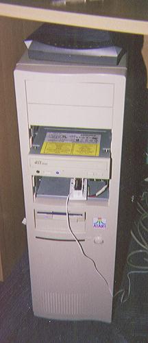
At this stage it
was almost completed, just finishing
the temperature display. |
|
Ahh,
as you can see the fans are
doing their job. |
|
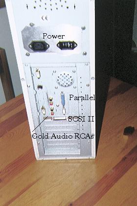
Here are the ports
lined up on the back panel.
The PSU's connectors were extended
to a panel made of 1mm thick
steel bolted in where the PSU
would normally sit. |
|
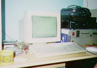
The finished product. |
Overall it
is a modification worth doing if you wish
to have more space and a decent PSU that
can cope with lots of hardware extensions.
Just can't wait to slot in the CT60!
|
![[ Advert ]](images/banner.gif)